


3
Siemens Building Technologies
Fire Safety & Security Products
04.2009
EN
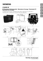
CIL0050-30 Installation Instruction
Package contents
•
1 x IR lamp (Fig. 1)
•
1 x power supply (Fig. 2)
•
2 M6 x 16 countersunk screws
•
2 M6 washers
•
2 M6 nuts
•
Installation
instructions
Target Group
The instructions contained in this document are intended for the following
target group:
Target
Group
Qualification
Activity
Condition of the
product
Installer
Must have technical
training for
electrical
installations.
Installing the
product, its
individual
components or
replacement parts.
The product's
individual
components are not
yet installed or
need to be replaced
or recalibrated.
Standards and guidelines
The product meets the requirements specified in the following EU directives.
The CE declaration of conformity is available from:
Siemens Building Technologies
Fire & Security Products GmbH & Co. oHG
76181 Karlsruhe
Germany
EU Directive 2004/108/EC on electromagnetic compatibility
Conformity with the EU Directive 2004/108/EC is demonstrated by compliance
with the following standards:
Emitted interference:
EN 61000-6-3
EN 55022 class B
Resistance to interference:
EN 50130-4
EU Directive 2006/95/EC on low voltage
Conformity with the EU Directive 2006/95/EC is demonstrated by compliance
with the following standard:
Safety: EN
60950-1
EN 60825-1
General safety precautions
•
Read the general safety instructions before installing the unit.
•
Follow the safety instructions attached to the unit.
•
Keep this document for later reference.
•
Keep this document with the product upon transfer.
•
Also follow the country-specific and local laws, guidelines and standards
for installing, operating and disposing of the product.
Liability claim
•
Only connect the device to the power supply if it is undamaged and all the
components were included in the package.
Transport
Unit damage during transport
•
Do not expose the unit to strong vibration or shock.
Installation
•
Do not look directly into the lamps for an extended period and not at a
distance of less than 1.5 meters.
Damage to equipment due to incorrect location
•
Observe the environmental requirements recommended by the
manufacturer. See technical data.
•
Install the device in a well ventilated area.
•
Only mount the device on stable and non-flammable surfaces.
Personal injury / fire hazard / damage to equipment due to incorrect
connection to the voltage supply
•
Connect the unit only to current sources with the voltage designated for
the device.
•
Make sure the device is permanently connected to the electricity supply; a
readily accessible disconnect device (16 A max.) must be provided.
•
The device is designed for TN electricity supply grids and IT electricity
supply grids in Norway with 230 V phase voltage. Do not connect the
device to other IT electricity supply grids.
•
Ground the unit according to the applicable local standards and
regulations.
Equipment damage / personal injury due to cable wear
•
Use the cable fittings that correspond to the cable's diameter.
•
Make sure that the strain relief is adequate for all of the cables coming out
of the device.
Service and maintenance
Risk of electric shock during maintenance
•
All maintenance or adjustments to the device should only be conducted by
trained professionals.
•
Disconnect the power supply cable and other connections from the power
supply before performing any maintenance work.
Function and design
IR illuminator
(Fig. 1)
1
Adaptive illumination (AI) bolt
2
IR illuminator
3
2 IR connections 2.5 m
4
Bracket
PSU
(Fig. 2)
1
Ground conductor
2
Photoelectric switch relay output
3
Telemetry input (volt-free input)
4
Photoelectric switch sensitivity
5
Mains input, 100 – 230 V AC
6
Photoelectric switch connection
7
IR lamp connection (polarity-sensitive)
8
IR lamp connection (polarity-sensitive)
9
IR Power adjust
10
photoelectric switch (photo cell)
11
12 V DC output for surveillance camera
Mounting and installation
Disconnect the PSU from the mains before removing the cover of the
PSU.
1.
Mount illuminator (Fig. 3, No. 1).
2.
Mount power supply unit (PSU) (Fig. 3, No. 2).
CAUTION
: Do not position the photoelectric switch facing illuminator
or other direct light sources. The photoelectric switch monitors
ambient lighting conditions. Mount PSU on wall/flat surface with
glands facing down.
3.
Connect illuminator to PSU (Fig. 2 no. 7, 8). Pay attention to the polarity
(
red = lamp+, black = lamp-
).
NOTE
: Extend or reduce lead length (max. distance 9 m with 0.75 mm
cable diameter) using appropriate cable and weatherproof box.
4.
If the IR illuminator is to be switched via an external contact, e.g. a camera,
disconnect the Bridge from the telemetry input (fig. 2, No. 3). Then
connect the external floating contact to the telemetry input. Also
disconnect the photoelectric switch from the control board.
– or –
In order to switch a camera with an IR lamp into night mode, connect the
camera's control input to the potential free output relay of the photoelectric
switch (Fig. 2, no. 2)
CAUTION
: Connect the ground conductor to the terminal provided for
this purpose on the housing (Fig. 2 Nr. 1).
5.
Connect PSU to mains (Fig. 2, Nr. 5).
CAUTION
: Ensure cable glands and PSU lid are watertight by
tightening the fixings (see technical data)
Setup
1.
Position illuminator adjacent to camera and point towards scene (ideally,
this should be done at night).
2.
Adjust vertical angle (Fig. 5).
3.
Adjust horizontal angle via adaptive illumination (AI) – if required (Fig. 6).
CAUTION
: Do not fully loosen the AI bolt.
4.
Tighten all fixings (Fig. 7).
5.
Match illumination to camera field of view.
Î
If step 5 does not match then repeat steps 2 to 4.
6.
Adjust scene illumination with power adjust (Fig. 2, No. 9) - if required
7.
Adjust Photoelectric switch sensitivity (Fig. 2, No. 4) – if required.
Содержание CIL0050-30
Страница 13: ......