Siemens Industry, Inc.
Building Technologies Division
P/N 315-033035-6
5
WIRING
At the top and bottom of the CC-5 and CC-2 and adjacent to each card slot are
removable terminal blocks. The wiring to the two terminal block connectors at the top
of the CC-5 and CC-2 is power limited. The wiring to the terminal block connector at
the bottom of the CC-5 and CC-2 is non-power limited.
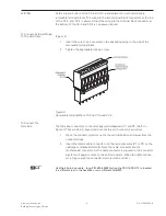
To Connect External Wiring
To The Card Slots:
(Figure 6)
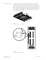
1.
Insert the wire to be connected in the desired opening in the side of the
removable terminal block.
2.
Tighten the appropriate locking screw.
Figure 6
Removable Terminal Block On The CC-5 and CC-2
To Connect The
Data Bus:
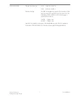
The Data bus connectors on the cardcage motherboard are P1 and P2. (Refer to
Figure 7.) They are 60 pin, keyed, male connectors with connector extractors.
1.
Open the connector ejectors out of the vertical position and away from the
connector body.
2.
Insert the female cable connector into the male connector (P1 or P2) on the
cardcage motherboard. Gently press the cable connector into the
motherboard connector. As the cable connector is pressed in, the connector
ejectors will begin to move to the vertical position. When the cable connec-
tor is fully seated the connector ejectors will be vertical.
Use the 60 pin bus cable - long, P/N 500-633997 when the PSC-12/PSX-12 is located
in a different row in the backbox or on a different CAB-MP.


