Siemens Industry, Inc.
Building Technologies Division
P/N 315-033035-6
2
PRE-INSTALLATION
The CC-5 and CC-2 are shipped with the card guides removed. The card guides are
keyed to assist in installation. They can be installed either before or after the cardcage
is installed in the enclosure. For ease of installation, the card guides have been
designed to be installed after the field wiring has been completed.
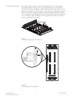
Card Guide Installation
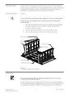
(Figure 3)
The upper and lower card guides are keyed differently and are not interchangeable.
Ensure that the card guide keys fit easily into the holes in the motherboard to
prevent damage.
1.
The upper card guide has a label on each slot that can be used to identify
the module installed in the slot. If desired, complete the label before
inserting the upper card guide.
2.
Insert the upper card guide and secure with the captive screws.
3.
Insert the lower card guide and secure with the captive screws.
GUIDE
PIN
GUIDE PIN HOLE
CAPTIVE SCREW RETAINERS
CAPTIVE SCREWS
LABELS
LOWER CARD GUIDE
UPPER CARD GUIDE
Figure 3
Card Guide Installation (CC-5 Shown)
INSTALLATION
Remove all system power before installation, first battery then AC. (To power up,
connect the AC first, then the battery.)
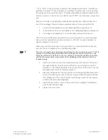
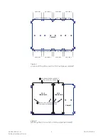
The CC-5 and CC-2 mount at the back of the enclosure of the FireFinder-XLS/Desigo
Fire Safety Modular/Cerberus PRO Modular system on the studs in the backbox or on
the optional Mounting Plate (CAB-MP). The Mounting Plate may be located either


