30
3D Reconstruction Upgrade Part 1
ARCADIS Orbic
SPR2-320.814.02.01.02
Siemens AG
01.05
CS SD 24
Page 30 of 46
Medical Solutions
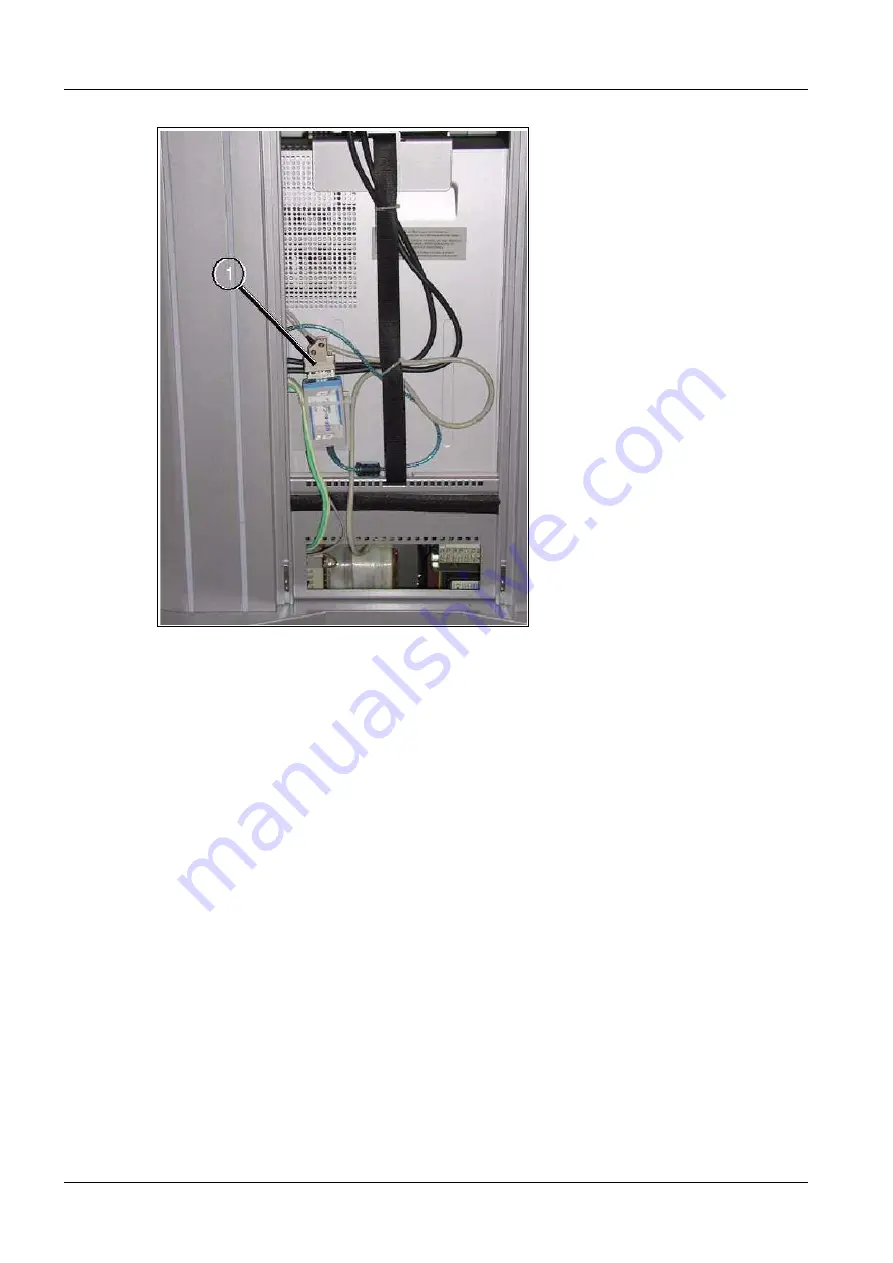
Fig. 22: Plug_1
•
Connect the USB plug of the USB/CAN converter to the PC (see
(1/Fig. 23 / p. 31)
).
Страница 1: ...en authority Offenders will be liable for damages All rights including rights created by patent grant or registration of a utility model or design are reserved Print No W ü r t h w e i n ARCADIS Orbic System Installation and Start up SP 2005 SPR2 320 814 02 01 02 Replaces n a English Doc Gen Date 01 05 3D Reconstruction ...
Страница 2: ...o order current revision levels Disclaimer The installation and service of equipment described herein is to be performed by qualified personnel who are employed by Siemens or one of its affiliates or who are otherwise authorized by Siemens or one of its affiliates to provide such services Assemblers and other persons who are not employed by or otherwise directly affiliated with or authorized by Si...
Страница 3: ...___________ 15 C arm 15 Limit switches 19 Setting the limit switches 20 Installing the system electronics for 3D reconstruction 71 39 921 22 Cable no 3 item number n a 25 Cable no 4 item number n a 26 Cable no 5A item number n a 26 Cable no 5B item number n a 26 Cable no 2 item number n a 26 Cable no 1 item number n a 26 Cable no 6 item number n a 26 Orbital drive cable set item no 71 39 970 28 In...
Страница 4: ...RCADIS Orbic SPR2 320 814 02 01 02 Siemens AG 01 05 CS SD 24 Page 4 of 46 Medical Solutions 2 1General Notes and symbols 0 Emphasized texts in technical documentation have the following meaning Fig 1 Safety notes ...
Страница 5: ...ctly follow The product specific safety information in these instruc tions The general safety information in instructions TD00 000 860 01 and The general safety information according to ARTD part 2 WARNING Electrical voltage Noncompliance can lead to death physical injury or property dam age Removing the system covers exposes voltage conduct ing parts To avoid danger always disconnect the sys tem ...
Страница 6: ... switched off for a longer period of time These electrolytic capacitors must be discharged before beginning work on the electrolytic capacitor batteries or on the generator To do this set switch D21 S2 to the UZ_OFF position and wait until LEDs D21 X22 and D21 X23 extinguish Then check the voltage between measuring points X109 UZ_IST ACT and X109 ANA_GND This voltage must equal 0 2V corre sponding...
Страница 7: ...ection guidelines and the rules for radiation protection according to ARTD 02 771 02 must be complied with Note Use available radiation protection devices Wear radiation protection clothing lead apron Maintain the greatest possible distance from the radia tion source Release radiation only if necessary Set the radiation activity as low as possible Low kV and mA values short radiation time Release ...
Страница 8: ...d places flat with a fine emery cloth and seal the damaged surface with paint A spray paint the color of the C arm can be used for this purpose see Service Tool Catalog Remove any carbon fibers lying in the C arm profile with a damp sponge or cloth If greater damage to the carbon fiber structure indicating persistent or large scale destruction of the carbon fiber structure e g crack formation or f...
Страница 9: ...ng cutting or grazing of the skin especially on the hands Perform the corresponding work with special care and attentiveness Wear work gloves if necessary CAUTION Danger of injury on mechanical parts Noncompliance can lead to minor to moderately severe injury es pecially to your hands When the covers are removed it is possible to come into contact with parts such as flat plugs threaded bolts cut o...
Страница 10: ...uipment and auxiliary devices 0 Standard installation tools Ground wire tester 44 15 899 RV 090 Torque wrench 99 00 846 RE999 Calibration phantom Iso C 3D with Navi 75 51 620 Drill with right left spiral clockwise counterclockwise n a Threader 96 60 093 DMM Fluke 8060A 97 02 101 Y4290 3D reconstruction upgrade kit 80 81 403 ...
Страница 11: ...1 Page 11 of 46 Medical Solutions Check list prior to installing the 3D option 0 Check the serial number A room suitable for the installation is available The tools to be provided by the R U are available All auxiliary service tools to be provided by the R U are available ...
Страница 12: ...cal Solutions Actions required prior to installing the 3D option 0 OK Not OK Functional check of the ARCADIS Orbic 3D in accordance with the operating manual Testing as part of the IQ quick test The Checking the ADR characteristics chapter The Resolution chapter The Image interference chapter ...
Страница 13: ... room and the brake has been enabled Cover of the X ray unit 0 Remove the cover and reattach it after installing the 3D option Horizontal carriage cover 0 Remove the cover and connector M3 X1 Reattach the cover after installing the 3D option Cable module cover 0 Remove the cover and dispose of it properly because this cover will no longer be re quired Attach the new cover after installing the 3D o...
Страница 14: ... 02 Siemens AG 01 05 CS SD 24 Page 14 of 46 Medical Solutions Centering disk item no 71 40 580 0 Fig 2 Centering disk Remove the countersunk screws prior to mounting the centering disk Attach the centering disk at the cable module see Fig 2 p 14 ...
Страница 15: ...flush with the top and mark the holes with the cam laterally at the 20 mm mark Fig 5 p 16 Punch mark the holes Ensure that shavings or dust do not drop into the C arm Use a 3 2 mm bit for drilling Continue until you have have drilled through the wall En sure that you are not drilling beyond the wall Fig 6 p 17 Counterbore the holes Cut the threads using an M4 thread tap e g use a tap wrench Fig 7 ...
Страница 16: ...16 3D Reconstruction Upgrade Part 1 ARCADIS Orbic SPR2 320 814 02 01 02 Siemens AG 01 05 CS SD 24 Page 16 of 46 Medical Solutions Fig 4 Mark distance Fig 5 Mark hole ...
Страница 17: ...Siemens AG SPR2 320 814 02 01 02 ARCADIS Orbic 01 05 CS SD 24 3D Reconstruction Upgrade Part 1 17 Page 17 of 46 Medical Solutions Fig 6 Drill Fig 7 Cutting the threads ...
Страница 18: ...AG 01 05 CS SD 24 Page 18 of 46 Medical Solutions WARNING Risk of injury on mechanical parts If these guidelines are not observed minor to moderate injury es pecially to the hands can occur Observe the safety notes concerning the C arm carbon fiber structure Fig 8 Attaching the cam ...
Страница 19: ...SPR2 320 814 02 01 02 ARCADIS Orbic 01 05 CS SD 24 3D Reconstruction Upgrade Part 1 19 Page 19 of 46 Medical Solutions Limit switches 0 Fig 9 Attaching both limit switches Fig 10 Limit switch in switching position ...
Страница 20: ...ge 20 of 46 Medical Solutions Attach the two limit switches at the cable module using M4 x 8 screws washers and contact washers Fig 9 p 19 Fig 10 p 19 Fig 11 p 20 Fig 11 Limit switch with cabling Fig 12 Setting the limit switch Setting the limit switches 0 Manually move the C arm into the end position ...
Страница 21: ...s Attach the two limit switches so that the cam enables the switching mechanisms at the switches Fig 12 p 20 When set correctly you can hear the click emitted by the limit switches Angulation 0 Test the functioning of the limit switches by moving the C arm into the 95 und 95 or bital positions Check these settings at least twice ...
Страница 22: ...CS SD 24 Page 22 of 46 Medical Solutions Installing the system electronics for 3D reconstruction 71 39 921 0 Fig 13 3D reconstruction system electronics D200 Fig 14 D1 Move the lifting column into the top position Remove the 4 upper mounting screws of D1 leave the washers on D1 Fig 14 p 22 ...
Страница 23: ...Orbic 01 05 CS SD 24 3D Reconstruction Upgrade Part 1 23 Page 23 of 46 Medical Solutions Attach the hexagonal bolts see Fig 15 p 23 Place D200 on the hexagonal bolts Attach D200 with the contact washers and nuts Fig 16 p 24 Fig 15 Mounted bolt ...
Страница 24: ...24 3D Reconstruction Upgrade Part 1 ARCADIS Orbic SPR2 320 814 02 01 02 Siemens AG 01 05 CS SD 24 Page 24 of 46 Medical Solutions Fig 16 Installed 3D reconstruction system electronics D200 ...
Страница 25: ...from PC board D1 Connect the plug to connector D200 X103 on interface PC board D200 Ensure proper locking On D30 reconnect plug D30 X5 to D200 X115 on interface PC board D200 For this purpose slip the cable out of the existing shielding and reinsert it from the opposite side On D30 reconnect plug D30 X12 to D200 X112 on interface PC board D200 For this purpose slip the cable out of the existing sh...
Страница 26: ...00 X212 D30 X12 Cable no 5B item number n a 0 Without the LITHOSTAR MODULARIS option Use ribbon cable no 5B to establish connection D200 X211 D30 X11 Cable no 2 item number n a 0 Disconnect plug D30 X4 on D30 Insert extension cable no 2 at plug D30X4A to D30 X4 Insert plug D200 X114 on PC board D200 Cable no 1 item number n a 0 Connect cable no 1 to plug D30 X4 on D30 and to plug D200 X214 on D200...
Страница 27: ...Siemens AG SPR2 320 814 02 01 02 ARCADIS Orbic 01 05 CS SD 24 3D Reconstruction Upgrade Part 1 27 Page 27 of 46 Medical Solutions Fig 18 Shielding connection D200 ...
Страница 28: ...0 is inserted into PC board D200 Fig 19 p 28 Proceed as follows with respect to the previously routed orbital drive cable set Insert plug D10 X11into plug in location D10 X11 on PC board D10 Insert plug D10 X10 into plug in location D10 X10 on PC board D10 Insert plug D200 X116 into plug in location D200 X116 on PC board D200 Insert plug D200 X221 into plug in location D200 x221 on PC board D200 ...
Страница 29: ...econstruction Upgrade Part 1 29 Page 29 of 46 Medical Solutions Installation USB CAN converter 0 Open the side and back covers of the monitor trolley see Fig 20 p 29 Secure the USB CAN converter see Fig 21 p 29 with cable ties see Fig 22 p 30 Fig 20 Covers Fig 21 Kit ...
Страница 30: ...construction Upgrade Part 1 ARCADIS Orbic SPR2 320 814 02 01 02 Siemens AG 01 05 CS SD 24 Page 30 of 46 Medical Solutions Fig 22 Plug_1 Connect the USB plug of the USB CAN converter to the PC see 1 Fig 23 p 31 ...
Страница 31: ...2 ARCADIS Orbic 01 05 CS SD 24 3D Reconstruction Upgrade Part 1 31 Page 31 of 46 Medical Solutions Fig 23 Plug_2 Fig 24 Plug_3 Connect the CAN plug see Fig 21 to the USB CAN converter 1 Fig 20 Close all covers of the monitor trolley ...
Страница 32: ...uction Upgrade Part 2 ARCADIS Orbic SPR2 320 814 02 01 02 Siemens AG 01 05 CS SD 24 Page 32 of 46 Medical Solutions 5 43D Reconstruction Upgrade Part 2 Orbital drive 0 Fig 25 Screws removed Fig 26 Attached motor unit ...
Страница 33: ... 24 3D Reconstruction Upgrade Part 2 33 Page 33 of 46 Medical Solutions Fig 27 Orbital drive fully installed Remove the two existing screws Fig 25 p 32 Attach the motor using 2 countersunk Allen screws M 8 x 40 Fig 26 p 32 Coupling unit 0 Fig 28 Centering disk ...
Страница 34: ... 34 of 46 Medical Solutions Fig 29 Coupling unit Fit the coupling unit onto the centering disk the shaft must engage with the connecting piece Fig 28 p 33 Press the coupling unit against the centering disk and attach it to the left and right using the two threaded pins Fig 29 p 34 Fig 30 Lateral bracket ...
Страница 35: ...rbic 01 05 CS SD 24 3D Reconstruction Upgrade Part 2 35 Page 35 of 46 Medical Solutions Fig 31 Lateral bracket_1 Attach lateral brackets Fig 30 p 34 on both sides Fig 31 p 35 first on top and then on the side use big washers Fig 32 Toothed belt ...
Страница 36: ...ical Solutions Fig 33 Belt tensioning Loosen the belt tightener at the coupling unit Fig 32 p 35 Install the wide toothed belt on the motor Fig 32 p 35 Tighten the belt On the opposite side of the belt tightener it should be possible to press the belt down approx 2 3 mm with your thumb Fig 33 p 36 Fig 34 Belt pulley ...
Страница 37: ...e orbital position limit switch side of image inten sifier Loosen the Allen screw at the belt pulley Fig 34 p 36 Attach the outside toothed belt see Fig 34 p 36 Use a screwdriver to turn the potentiometer counterclockwise into the end position Fig 35 p 37 Once the potentiometer is in this position turn it fully clockwise twice Secure the belt pulley with the Allen screw Fig 34 p 36 ...
Страница 38: ...D Reconstruction Upgrade Part 2 ARCADIS Orbic SPR2 320 814 02 01 02 Siemens AG 01 05 CS SD 24 Page 38 of 46 Medical Solutions Angulation measurement 0 Fig 36 Mounting screw Fig 37 Square bar in cable module ...
Страница 39: ...unted angulation part with marking Fig 39 Installed angulation part Remove the square bar from the cable module see Fig 38 p 39 and Fig 39 p 39 Move the angulation part into the cable module and attach it with screws Fig 41 p 40 Ensure that the markings black lines on the two gear wheels match exactly Fig 40 p 40 Secure cables with cable ties ...
Страница 40: ...e cover from the encoder Fig 43 p 41 Fig 42 p 41 shows the plugs from the limit switch cable of the orbital drive Connect the encoder plug of the encoder cable to the encoder plug under the cover Connect the angulation plug of the cable of the angulation part to the X4 plug of the or bital drive cable set Connect the limit switch plug of the limit switch cable to the limit switch plug of the orbit...
Страница 41: ...SD 24 3D Reconstruction Upgrade Part 2 41 Page 41 of 46 Medical Solutions Fig 42 Terminal blocks Fig 43 Shielding Secure the shielding and attach it with screws Fig 45 p 43 Connect cables 1 through 4 to terminal blocks 1 through 4 Fig 44 p 42 and Fig 46 p 43 ...
Страница 42: ...Orbic SPR2 320 814 02 01 02 Siemens AG 01 05 CS SD 24 Page 42 of 46 Medical Solutions Fig 44 Connecting the terminal block Clamp the red cable of the coupling unit to terminal block 3 Clamp the blue cable of the coupling unit to terminal block 4 ...
Страница 43: ...Siemens AG SPR2 320 814 02 01 02 ARCADIS Orbic 01 05 CS SD 24 3D Reconstruction Upgrade Part 3 43 Page 43 of 46 Medical Solutions 6 53D Reconstruction Upgrade Part 3 Fig 45 Labels_1 Fig 46 Label_3 ...
Страница 44: ...and small label for 3D reconstruction to the unit as shown in a b Fig 45 p 43 Affix the safety label to the cover of the cable module as shown in Fig 46 p 43 Also affix the second safety label to the cable module cover on the opposite side of the other label Affix the 3D label to the ARCADIS Orbic C arm see 1 Fig 46 p 43 and the monitor trolley see 1 Fig 47 p 44 ...
Страница 45: ...ables in the zipper hose to the basic unit Connect the monitor trolley to the line voltage Release the orbital brake Manually move the C arm into both end positions The movement has to correspond to normal C arm movement If not verify that connector M3 X1 for the brake assembly is inserted correctly If yes the LEDs in both keys light up The next step 0 Continue with ARCADIS Orbic Start up Instruct...
Страница 46: ...46 Changes to the Previous Version ARCADIS Orbic SPR2 320 814 02 01 02 Siemens AG 01 05 CS SD 24 Page 46 of 46 Medical Solutions 8 7Changes to the Previous Version n a new version ...