Siemens 985-047 Скачать руководство пользователя страница 7

129-287 

Operating Instructions 

Rev. 1, October, 1999 


Siemens Industry, Inc.


Page 7 of 8 


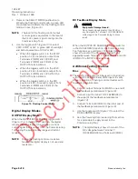
Figure 14.  Bias Output.  


Voltmeter 


WARNING

Shock Hazard.


Disconnect all power supplies to the 
Commissioning Tool and actuator or control 

device before wiring to avoid possible 
electrical shock or equipment damage. 


The DC FEEDBACK input may be used as a 
DC voltmeter to measure up to 30 Vdc.  

1.


Connect Terminal 7 (DC FEEDBACK) of the 
INPUTS terminal block to the positive side of the 
voltage to be measured (

Figure 15

).  

2.


Connect Terminal 8 (COM) of the INPUTS 
terminal block to the minus or common side of 
the voltage to be measured. 


Figure 15.  Voltmeter Connections.  

3.


Use the toggle switch (

Figure 11

) to select the 

DC FEEDBACK display mode.  

4.


See the 

Powering Commissioning Tool 

section 

for a procedure to apply power to the 
Commissioning Tool. 

NOTE:


The digital display shows the level of the 
DC voltage applied between Terminal 7 
(DC FEEDBACK) and Terminal 8 (COM). 


Auxiliary Switch Testing 


CAUTION

Equipment Damage Hazard. 

Do not apply power to the switch being tested 

or to the Commissioning Tool auxiliary switch 
inputs. The Commissioning Tool provides a 
signal to the switch contacts being tested. 

 
Auxiliary switch testing can be used independently 
or while supplying a control signal to the field 
devices. LEDs display auxiliary switch contact 
closure.  

NOTE:


Connect the auxiliary switch terminals to 
dry contacts only. 

1.


Connect the control device’s auxilia

ry switch 

terminals to the applicable Commissioning Tool 
auxiliary switch input terminals (

Figure 16

).  


Figure 16.  Switch Connections Using 

Dry Contacts.  

2.


See the 

Powering Commissioning Tool 

section 

for a procedure to apply power to the 
Commissioning Tool. 

3.


LEDs at the bottom right of the Commissioning 
Tool activate or de-activate when their 
respective switch contact closes or opens. Also 
see the appropriate actuator documentation for 
switch wiring information. 


Repair 


CAUTION

Field repairs must not be made.  


Содержание 985-047

Страница 1: ... DC voltage and current for controlling an actuator It requires no controller hook up which makes equipment calibration setup and adjustment a quick and easy process Figure 1 Actuator Commissioning Tool Features and Benefits Universal Compatibility Works with all Siemens actuators most competitors actuators and other voltage current or resistance controlled equipment Compact Portable Unit Allows e...

Страница 2: ...l 24 Vac nominal for use with floating control and on off actuators The resistive mode is the default operating mode when the commissioning tool is not powered To select other operating modes the ON OFF switch must be turned ON LEDs indicate which mode is active The Commissioning Tool also provides additional testing features as follows Table 2 Additional Testing Features Feature Function Power fo...

Страница 3: ...igher voltages could damage the device Powering a Non externally Powered Actuator or Control Device CAUTION Equipment Damage Hazard Controlled equipment loading from Terminals 1 and 2 must be limited to 25 VA maximum NOTE For 115 230 Vac actuators the Commissioning Tool can be used to provide signal but must be externally powered 1 To provide a 24 Vac nominal power signal connect Terminals 1 24 Va...

Страница 4: ...or a procedure to apply power to the Commissioning Tool 5 If the resistive mode green LED Figure 7 does not light depress the SELECT MODE pushbutton to activate the resistive mode The green LED should then light and indicate that the resistive mode is active 6 Turn the dial Figure 7 to adjust the level of resistance Figure 7 Resistive Mode Proportional Voltage Mode Vdc 1 To supply a 0 to 20 Vdc si...

Страница 5: ...ing Tool section for a procedure to apply power to the Commissioning Tool 5 Depress the SELECT MODE pushbutton to activate the current mode A green LED should light and indicate that the current mode is active Figure 11 6 Use the rocker switch located on the upper left side of the Commissioning Tool Figure 11 to adjust the current level from 0 to 20 mA The digital display shows the level of the ou...

Страница 6: ...tput from the Commissioning Tool during the proportional voltage and current modes NOTE During the floating control or resistive modes the digital display is not used and reads zero DC Feedback Display Mode CAUTION Equipment Damage Hazard Do not apply signals greater than 30 Vdc or any AC signals to Terminal 7 DC FEEDBACK or damage to the Commissioning Tool can result When the OUTPUT DC FEEDBACK t...

Страница 7: ...C voltage applied between Terminal 7 DC FEEDBACK and Terminal 8 COM Auxiliary Switch Testing CAUTION Equipment Damage Hazard Do not apply power to the switch being tested or to the Commissioning Tool auxiliary switch inputs The Commissioning Tool provides a signal to the switch contacts being tested Auxiliary switch testing can be used independently or while supplying a control signal to the field...

Страница 8: ... ohms 7 2W or 0 to 1k ohms 5 2W Terminals 3 4 and 5 Proportional Voltage 0 to 10 Vdc 500 ohms minimum 0 to 20 Vdc 6 8k ohms minimum Terminals 2 and 3 Current 0 to 20 mA 680 ohms maximum Terminals 2 and 3 Floating Control 24 Vac nominal 20 to 30 Vac 25 VA maximum Terminals 2 3 and 4 Output AC voltage is equivalent to the input AC voltage and frequency Bias 5 Vdc with 330 ohm series resistor Termina...

Отзывы: