

129-287
Operating Instructions
Rev. 1, October, 1999
Siemens Industry, Inc.
Page 5 of 8
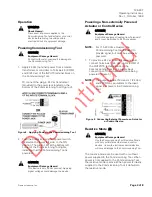
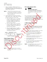
6.
Use the rocker switch located on the upper left
side of the Commissioning Tool (
Figure 9
) to
adjust the voltage level from 0 to 20 Vdc. The
digital display shows the level of the output
voltage. (Adjustment increments increase 0.1V
during the first five seconds and then increase
rapidly after that, allowing for quick adjustment
of the output control signal.)
Figure 9. Voltage Mode.
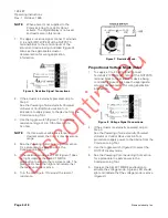
Proportional Current Mode (mA)
1.
To supply a 0 to 20 mA signal, connect
Terminals 2 (COM) and 3 (mA) of the OUTPUTS
terminal block to the actuator or device being
controlled (
Figure 10
). Also see the appropriate
actuator documentation for wiring application
information.
Figure 10. Current Signal Connections.
2.
If the actuator is externally powered, skip to
Step 3.
See the
Powering a Non-externally Powered
Actuator or Control Device
section for a
procedure to apply power to the device from the
Commissioning Tool.
3.
Use the toggle switch (
Figure 11
) to select the
OUTPUT display mode.
4.
See the
Powering Commissioning Tool
section
for a procedure to apply power to the
Commissioning Tool.
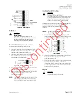
5.
Depress the SELECT MODE pushbutton to
activate the current mode. A green LED should
light and indicate that the current mode is active
(
Figure 11
).
6.
Use the rocker switch located on the upper left
side of the Commissioning Tool (
Figure 11
) to
adjust the current level from 0 to 20 mA. The
digital display shows the level of the output
current. (Adjustment increments increase
0.1 mA during the first five seconds and then
increase rapidly after that, allowing for quick
adjustment of the output control signal.)
Figure 11. Current Mode.
Floating Control Mode (Vac)
NOTE:
The digital display is not used and reads
zero in this mode.
1.
Connect Terminals 2 (COM), 3 (CCW), and 4
(CW) of the OUTPUTS terminal block to the
actuator or device being controlled (
Figure 12
).
Connect Terminal 1 (24 Vac) for spring return
actuators (
Figure 5
).
NOTE:
On removal of the Terminal 1 connection,
the actuator spring return activates. Also
see the appropriate actuator
documentation for wiring application
information.
Figure 12. Floating Control Signal Connections.
NOTE:
Verify that the toggle switch is in the
STOP position (
Figure 13
.).
2.
See the
Powering Commissioning Tool
section
for a procedure to apply power to the
Commissioning Tool.


