A5E00721185
7
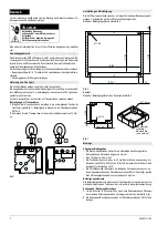
Fig. 4
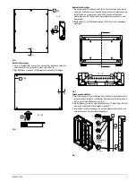
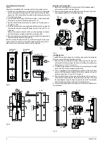
Mounting the top cover
1
10x5 mm sealing tape must be attached all around the top cover to achieve
IP54 degree of protection. See Figure 5 (
a
).
2
Mount the top cover from the outside with sheet metal screws M 5.
Fig. 5
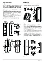
Mounting the bottom plate
1
Bolt the mounting angles to the vertical inner leg of the front and back cross
members using M 8x15 threaded bolts, 8 contact washers and M 8 hexagonal
nuts. See Figure 6. The front surface of the mounting angle and the upper
edge of the cross member leg must be on the same plane.
2
Mount the bottom plate to the mounting angles with PM 5x10 sheet metal
screws.
Fig. 6
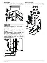
Installing the internal partition
1
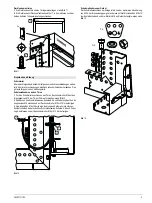
Insert the rubber spacers at regular intervals into the respective rows of holes
of the two frames to be joined laterally. The distance between the row of holes
and the outer edge of the frame is 60 mm.
2
Mount the internal partition using four M 8x15 threaded bolts, distance
washers, 8 contact washers and M 8 four nuts each. See Figure 7.
3
Place the frames next to each other and join them together to form cabinet
groups (see sub-section “Cabinet groups”).
Fig. 7
$$
$
$
D
%
%
%%
D
&&
&
&
[
0
[
0[
'LVWDQ]ULQJ
6SDFHU


