A5E00721185
9
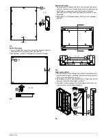
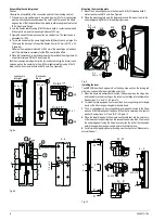
Mounting the trimstrip
1
Place the trimstrip on the upper door support angles according to Figure 11.
2
Screw the trimstrip into the center hole of the two outer door support angles
using M 5x17 pan head screws.
Fig. 11
Protective conductors
All cabinet connections not mentioned in the following section are already
connected to each other using electrically conductive screw connections. The
same applies to powdered paneling parts.
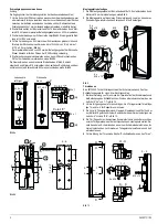
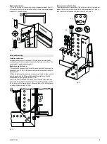
Measures to protect the door
1
Screw the M 6 hexagonal nuts to the M 6 grounding stud of the door with a
tightening torque of 3 Nm for the protective conductor connection of the doors.
See Figure 12.
2
Place the cable lug of the protective conductor wire, the A 6.4 washer, and the
6 spring washer onto the M 6 grounding stud and secure them with a M 6
hexagonal nut using a tightening torque of 7 Nm.
3
Insert the M 6x15 threaded bolt through one of the holes of the side frame,
attach the 6 contact washer, the cable lug of the protective conductor wire, the
A 6.4 washer and the 6 spring washer, and secure them with a M 6 hexagonal
nut using a tightening torque of 12 Nm.
Fig. 12
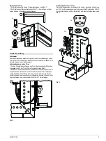
Measures to protective the frame
The protective conductor connection of the system is suitable for a maximum
infeed of 630 A and must be mounted to the frame using three 8x15 draw-in
bolts, three 8 contact washers and three M 8 nuts. See Figure 13.
Fig. 13
Safety and Grounding
[
[
[
[


