background image


76


Revision 04 * INSTALLATION AND  OPERATING INSTRUCTIONS 8BT2 * 881-4027.9


Result 


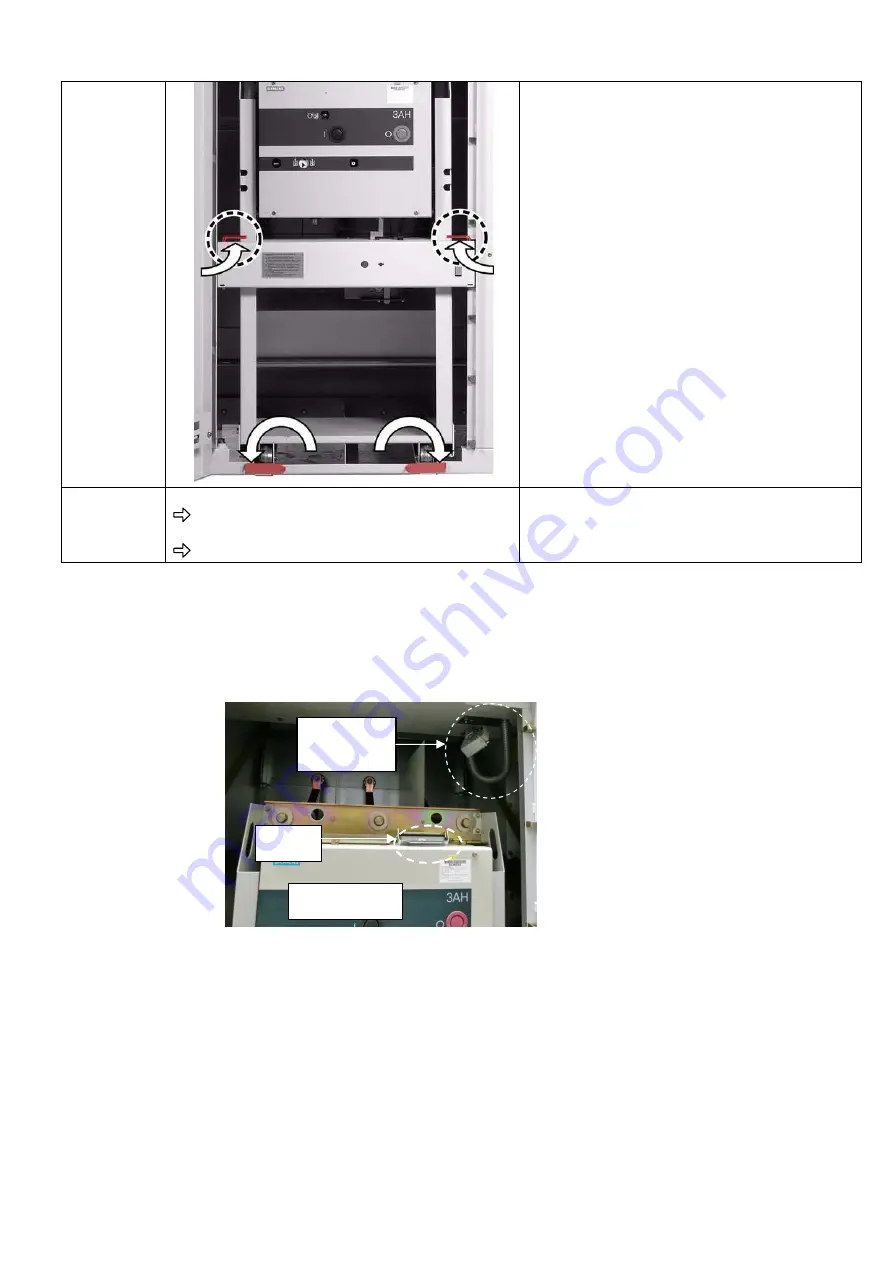
The switching device truck is inserted and locked. 

  Plug the voltage connector in and latch the 

connector lock tight down wards. 

  Close the high voltage door. 


The switching device truck is moved out of the 

panel. 


6.7.     Low voltage plug connection and coding


Plug connection


All control wires related to the circuit breaker’s internal circuit are connected to the low voltage 
connector (fig82). 


Fig82. View of the low voltage connector and socket.


After inserting the witdrawable truck into the test position in the panel, the connector should be 
plugged into the socket on the circuit breaker to be able to provide the electrical connection 
between the circuit breaker’s and the low voltage control circuits (Please see fig83 for the 
connection). 

Low voltage 
connector 

Circuit breaker 

socket 

Содержание 8BT2

Страница 1: ...ype 8BT2 Extendable Truck Type Circuit Breaker Switchgear up to 36kV Metal Enclosed Indoor Installation LSC2B PM SingleBusbar Air Insulated INSTALLATION AND OPERATING INSTRUCTIONS Order No 881 4027 9 Revision 04 Issue 26 03 2019 ...

Страница 2: ... reserve the right to modify the specified values and drawings All dimensions are given in mm For further details e g about additional equipment and information about other switchgear types please refer to catalog HA 26 41 Should further information be desired or should particular problems arise which are not covered sufficiently by these instructions the matter should be referred to the competent...

Страница 3: ...ear 46 4 3 6 Assembly of the low voltage compartment on request 46 4 3 7 Assembly of the arc routing plates 47 4 3 7 1 Gas pressure relief from the ear 48 4 3 7 2 Gas pressure relief from the top 49 4 3 8 Assembly of the closed relief duct 51 4 3 9 Electrical connections 56 4 3 9 1 Power cable connection 56 4 3 9 1 1 Front access of the panel 58 4 3 9 1 2 Rear access of the panel 61 4 3 9 1 3 Deep...

Страница 4: ...instructions given in these operating instructions the local laws ordinances guidelines and standards for operation of electrical equipment as well as for labor health and environmental protection apply Any kind of modification on the product or alteration of the product must be coordinated with the manufacturer in advance as uncoordinated modifications or alterations can cause the expiration of w...

Страница 5: ...nnel must have taken part in the training for assembly and installation of Siemens air insulated medium voltage switchgear type 8BT2 This installation training provides detailed information about design operation installation and trouble shooting on the primary part of 8BT2 switchgear After successful participation the participants in this training get a certificate This certificate authorizesthe ...

Страница 6: ...6 Revision 04 INSTALLATION AND OPERATING INSTRUCTIONS 8BT2 881 4027 9 ...

Страница 7: ...l standing version and from front rear for free standing version Designed as truck type switchgear circuit breaker Panel internal control cables routed in metallic wiring ducts or steel spiral tubes Cable testing without de energizing the main busbars possible by using the lower shutter opening tool Extension of existing switchgear at both ends without modification of panels Use of block type curr...

Страница 8: ... dirt and dust SWITCHGEAR Wall standing type Free standing type 1 without the closed pressure relief duct 2 with the closed pressure relief duct 1 without the closed pressure relief duct 2 with the closed pressure relief duct NOTE To install the switchgear the room must have the certain minimum dimensions Please observe the following illustrations Rated short time withstand current kA Without the ...

Страница 9: ... to reach the rear of the switchgear 800 mm when the short circuit current is 31 5kA 4 Control aisle for panel replacement from ground area of existing panels 3000 mm Note Foundation details are shown on pages 24 and 25 2 with the closed pressure relief duct Remarks 3 in between the panel s side wall and the room s wall 100 mm or less than this value PLEASE CONSULT SIEMENS company 500 mm standard ...

Страница 10: ...ference point is the related panel s arrangement as seen in fig1 The gap X dimension between lateral side of the switchgear and the wall is important to identify the location of wall opening The aisle at the back side of the switchgear Y dimension determines the length of the outlet channel It should be specified during the order stage to be able to produce the suitable exhaust channels 2 1 4 2 Ou...

Страница 11: ...foreign objects Protected against solid foreign objects diameter 12 5 mm Protection against electric shock Protected against access to hazardous parts with a finger the jointed test finger of 12 mm diameter 80 mm length shall have adequate clearance from hazardous parts 2 1 6 Basic prescriptions and standards IEC EN Standard VDE Standard Switchgear 62271 1 0670 1 62271 200 0671 200 Switching devic...

Страница 12: ... electrically bonded to be able to carry high frequencies and contacted concentrically at the cable ends The shields of cablesand wires are connected and earthed in the low voltage compartment Connect the shields to earth potential with high electrical conductivity and all around as far as possible Protect the contact surfaces from corrosion in case of humidity regular condensation When laying cab...

Страница 13: ...Annex III Section 5 up to rated short duration power frequency voltage rated power frequency withstand voltage stipulated in accordance with IEC DIN VDE 2 1 11 Operating conditions 8BT2 switchgear is designed for normal indoor operating conditions according to IEC 62271 1 In this respect the following limit valuesfor the ambient air temperature must be complied with as a minimum The ambient air te...

Страница 14: ... Please see IEC 62271 1 2007 clause 2 2 1 2 2 Panel design 8BT2 truck type circuit breaker switchgear consists of various panel types which can be freely combined according to the requirements Basic design Enclosure made of galvanized sheet steel Front doors and lateral switchgear end walls are powder coated with resistant epoxy resin Material Individual modular compartments in solid wall design M...

Страница 15: ... capacitive voltage detection Busbar voltage transformers Make proof busbar earthing switch Transverse busbar partition from panel to panel and busbar insulation C Cable compartment Rated normal feeder current Ir A Single core XLPE cables Three core XLPE cables 1 Quantity per phase Conductor cross section mm Quantity per phase Conductor cross section mm 1250 2 500 2 300 1250 2000 4 500 2000 3150 6...

Страница 16: ...for busbar in the bussectionaliser panel with short circuit making capacity Earthing switch for busbar with short circuit making capacity Earthing switch for feeder with short circuit making capacity Earthing switch for busbar with short circuit making capacity Capacitive voltage detecting system Capacitive voltage detecting system Capacitive voltage detecting system Capacitive voltage detecting s...

Страница 17: ...nel which the circuit breaker is available Bus riser panel is naturally ventilated Fig5 Natural ventilation for 2500A rated current Fig6 Air forced ventilation for 3150A rated current Z detail In the normal operation After an internal arc fault Fig7 Working condition of the ventilation flap on high voltage compartment door Hot gas pressure due to an internal arc fault Red colored flag Air flow for...

Страница 18: ...ated mechanical interlock for operating mechanism with vacuum circuit Mechanical position indicators for circuit breaker breaker Truck firmly interlocked with panel Manual operation of the switching device truck mechanism The control cables of the truck are connected with the panel through a low voltage plug connector to be coupled manually when the circuit breaker truck is inserted in the panel A...

Страница 19: ...g operation and the instant when the contacts touch in all poles Opening time The interval of time between the initiation command of the opening operation and the instant when the contacts separate in all poles Arcing time The interval of time from the first initiation of an arc and the instant of final arc extinction in all poles Break time The interval of time between the initiation command of t...

Страница 20: ...door If the switching device truck is in the panel Switching device truck is in TEST position Closing the high voltage door If the switching device truck is in the panel Low voltage plug connector on circuit breaker is plugged in and locking gates of guide rails are closed Racking the switching device truck to SERVICE position High voltage door is closed and feeder earthing switch is open Racking ...

Страница 21: ...king the withdrawable part Operating lever for the feeder and the busbar earthing switches Hand crank for racking the switching device truck in and out Hand crank for manual charging of the circuit breaker s closing spring in SERVICE position Lower shutter opening tool Operating lever for the withdrawable voltage transformers mechanism ...

Страница 22: ... length 3m Test equipment for the pressure switch KP incandescent lamp voltage indicator with operating rod 12kV HV HRC fuse links Cable lugs adapter systems Surge arresters HR voltage indicators Test units to check the capacitive interface and the voltage indicators fig8 Phase comparison test units for capacitive voltage indicators type EPV HR e g Pfisterer including 2HR LRM adapters and storage ...

Страница 23: ...8BT2 switchgear can be disposed of as classified materials Please observe the local regulations for disposal and environmental protection Transport unit The switchgear is delivered in transport units These consist of individual switchpanels without fitted busbars Accessories are packed separately and included with the switchgear Transport weights dimensions with packing Panel type Domestic packing...

Страница 24: ...ort units in such a way that the can be taken out later in the correct order for installation Switchgear storage As a rule the switchgear should be stored in a closed room The storage room must have in closed room the following characteristics Floor with adequate load bearing capacity weights as per delivery note Even floor to enable stable storage Well ventilated and free of dust as far as possib...

Страница 25: ...r building with the locations and dimensions of doors and other narrow points as well as the floor number of the installation room Information about available lifting equipment e g mobile crane fork lift truck lifting truck hydraulic jack roller pads If no lifting equipment is available please notify this explicitly 4 1 1 General site requirements Before starting the installation of the switchgear...

Страница 26: ...e62 and 63 for the detail information 4 1 4 Tools These instructions Measuring sheet of the base frame Lifting truck Several roller pads reinforced rollers Several strong boards Rope or chain with transport shackles Transport rods diameter 25 to 30mm Reinforcing bars roller crowbars Torque wrench 6 260 Nm Shim plates 0 5 to 1 mm Phase tape L1 L2 L3 gn ye Shell VASELINE 8422 DAB 8 0 250 kg tube ord...

Страница 27: ...n the transport units as close to the switchgear building as possible in order to avoid unnecessary ways Move the transport units into the building Only remove packing where absolutely necessary in order to keep the switchgear as clean as possible 4 2 1 Unloading by forklift Unloading the transport units from the truck should be done by a forklift fig10 Fork length 1500 mm Insert the lifting forks...

Страница 28: ...tallation Check whether the delivery is complete using the delivery note and packing lists If the delivery is incomplete inform the regional SIEMENS representative Repack the switchgear as far as possible and reasonable Do not remove the PE foil until reaching the mounting position in order to keep the switchgear as clean as possible 4 2 4 Transport to the installation place switchgear room Thorou...

Страница 29: ...g ATTENTION For further transport of a cubicle with a floor conveyor or other means of transportation reinforced rollers etc a minimum live load of 14 5 kN m2 must be considered Non observence of the live load can endanger people or damage the transport units during further transport Please ensure that the lifting and transport gear used meets the requirements regarding to construction and load be...

Страница 30: ...he materials and auxiliary devices required for installation 4 3 Assembly of the switchgear To assemble the switchgear the below steps should be followed Align the panels by using fixing tools Bolt the panels together Fasten the panels to the foundation Open the busbar comparment Assemble and interconnect the busbars Close the busbar comparment Assemble and interconnect the earthing busbars Instal...

Страница 31: ...bolted together from inside Set nuts for interconnecting the panels are together pressed into the left part of the panel frame i e the panels are bolted together from the right side to the left panel The following illustration shows the panel joints in circles fig16 Fig16 Panel joints marked in the illustration with a circle Using the fixing The fixing tools from the supplementary equipment facili...

Страница 32: ...ded in the panel floor In the foundation an elongated hole 25 x 45 mm has been provided each Fasten every panel to the foundation at these three points Wall standingtype Free standing type Detailed foundation drawings Pos nrs Floor fixing points Opening dimensions 25 x 45mm Floor opening for low voltage control cables Floor opening for high voltage power cables Switchgear end wall Note X Y Z T dim...

Страница 33: ...eter of 10 mm including the matching screws Remove any dirt occurred during drilling or welding work Extreme cleanliness is required during installation Now the switchgear is fastened to the foundation 4 3 3 Assembly of the busbars Feeder and Coupling panels When the switchgear is installed the busbars can be interconnected between panels The busbars are temporarily attached to panels for transpor...

Страница 34: ...s under the voltage Longer the bolt is used more risks it is taken at the insulation The threads of the bolts and nuts must be dry and non greasy Check contact surfaces of busbars brush if necessary and apply a thin film of Shell Vaseline 8422 DAB 8 NOTE The strain washers at the busbars have one side cambered inwards and one side cambered outwards Observe correct position of strain washers for as...

Страница 35: ...0 40x10 or 80x10 M12x40 M12 80x10 2x40x10 M12x50 M12 2000A 2x80x10 40x10 or 80x10 M12x50 M12 2x80x10 2x40x10 M12x60 M12 2500A 3150A 3x80x10 40x10 or 80x10 M12x60 M12 3x80x10 2x40x10 or 2x80x10 M12x70 M12 3x80x10 3x80x10 M12x75 M12 Please see the below drawings related to the connection details between main busbars dropper bars and intermediate copper spacers according to the different combination ...

Страница 36: ...4 INSTALLATION AND OPERATING INSTRUCTIONS 8BT2 881 4027 9 Fig21 Main busbar Dropper bars ratings _ 1250A 1250A Fig22 Main busbar Dropper bars ratings _ 2000A 800A Fig23 Main busbar Dropper bars ratings _ 2000A 1250A ...

Страница 37: ...TION AND OPERATING INSTRUCTIONS 8BT2 Revision 04 37 Fig24 Main busbar Dropper bars ratings _ 2000A 2000A Fig25 Main busbar Dropper bars ratings _ 2500A 3150A 800A Fig26 Main busbar Dropper bars ratings _ 2500A 3150A 1250A ...

Страница 38: ...OPERATING INSTRUCTIONS 8BT2 881 4027 9 Fig27 Main busbar Dropper bars ratings _ 2500A 3150A 2000A Fig28 Main busbar Dropper bars ratings _ 2500A 3150A 2500 3150A 4 3 4 Busbar compartment separation Optional Insulated separation plate ...

Страница 39: ...nstructions for Diagram1 in fig29 32 on pages40 43 for Diagram2 in fig33 on page44 ATTENTION Please ensure that the bolt directions are applied correctly as mentioned at fig29 fig33 It is important to provide the sufficient clearances between phases and earthed parts Apply the exact bolt sizes listed in below table due to the critical electrical clearances between live parts under the voltage Long...

Страница 40: ...and one side cambered outwards Observe correct position of strain washers for assembly Mount the strain washers so that the side cambered outwards points at the bolt head or the nut NOTE Bolt types for connections of lower main busbars Hexagon head bolt without nut used only at Current Transformer or Post Insulator connections in the sectionalizing panel Mushroom head bolt with nut used at connect...

Страница 41: ...027 9 INSTALLATION AND OPERATING INSTRUCTIONS 8BT2 Revision 04 41 Sectionalizing panel at the left hand side Busriser panel at the right hand side Sectionalizing Busriser Fig29 800A Assembly of Coupling bars ...

Страница 42: ...42 Revision 04 INSTALLATION AND OPERATING INSTRUCTIONS 8BT2 881 4027 9 Fig30 1250A Assembly of Coupling bars ...

Страница 43: ...881 4027 9 INSTALLATION AND OPERATING INSTRUCTIONS 8BT2 Revision 04 43 Fig31 2000A Assembly of Coupling bars ...

Страница 44: ... panel at the right hand side Busriser panel at the left hand side When locations of Sectionalizing and Busriser panels are reversed the assembly of lower main busbar is also reversed Please see the below sample for 2500A 3150A rating assembly the same method is available for other ratings 800A 1250A 2000A Busriser Sectionalizing ...

Страница 45: ...s as done in fig33 4 3 4 4 3 5 Earthing 4 3 5 1 Interconnecting the earthing busbars The earthing busbars in panels are pre assembled at the factory When the switchgear is installed the busbars can be interconnected between panels via the copper bridges which are provided as accessory NOTE Each panel has a fixed earthing bar in the cable compartment The intermediate copper bridge to interconnect t...

Страница 46: ...tion at least the earthing busbar of the left and right end panel to the substation earth of the switchgear building The connection is available in every panel either in the cable compartment or in the switching device compartment 4 3 6 Assembly of the low voltage compartment on request On request the low voltage compartments can be delivered separately and must be mounted on site ATTENTION The lo...

Страница 47: ... 8 at page49 for the closed pressure relief duct assembly ATTENTION Risk of injury Be aware of the sharp edges of steel parts during the assembly of the pressure relief ducts ATTENTION Arc routing plates have enough weight to endanger people Do not stay under a suspended arc routing plates before completion of assembly Preparations Procedure to be followed if accessibility to the panels is insuffi...

Страница 48: ...ble to apply arc routing plates efficiently min distances fig37 should be considered Fig38 Assembly of arc routing plates Arc routing plates pos nr in fig38 are mounted to side holes at the top of the switchgear as shown in fig38 and fig39 Left and right rear side walls pos nr in fig38 are used to prevent any hot gas damage on people in the switchgear room Fig39 Final assembly of the arc routing p...

Страница 49: ...NOTE The following application is valid up to 25kA short circuit current Fig40 Side view and front view To be able to apply arc routing plates efficiently the above min distances should be considered Fig41 Assembly of arc routing plates Fig42 Final assembly of the arc routing plates at the free standing switchgear version 25kA ...

Страница 50: ... is valid up to 31 5kA short circuit current Fig43 Side view and front view To be able to apply arc routing plates efficiently the above min distances should be considered Fig44 Assembly of arc routing plates Fig45 Final assembly of the arc routing plates at the free standing switchgear version 31 5kA ...

Страница 51: ...of injury Be aware of the sharp edges of steel parts during the assembly of the pressure relief ducts ATTENTION Pressure relief ducts have enough weight to endanger people Do not stay under a suspended pressure relief duct before completion of assembly Preparations Procedure to be followed if accessibility to the panels is insufficient in the final position Mount the pressure relief duct onto corr...

Страница 52: ...e assembly Lateral exit Fig46 Closed pressure relief duct with lateral exit Assembly of the closed pressure relief duct with lateral exit Fig47 Assembly of the closed pressure relief duct Pos nr in fig47 Endplate It is assembled on the right or left end panel Closed pressure relief duct Exhaust channel lateral exit ...

Страница 53: ... pos nr depends on the distance between the switchgear and the wall The intermediate frame pos nr is used whenever the number of exhaust channel group pos nr is more than one fig48 The connection details of the frame pos nr to the wall outlet are shown in fig49 Fig49 Wall opening details for lateral exit Pressure relief flaps Z detail Z detail ...

Страница 54: ...TRUCTIONS 8BT2 881 4027 9 Rear exit Fig50 Closed pressure relief duct with rear exit Assembly of the closed pressure relief duct with rear exit Fig51 Assembly of the closed pressure relief duct Closed pressure relief duct Exhaust channel rear exit ...

Страница 55: ...channels pos nr depends on the distance between the switchgear and the wall The intermediate frame pos nr is used whenever the number of exhaust channel pos nr is more than one The connection details of the frame pos nr to the wall outlet are as below Fig53 Wall opening details for lateral exit Pressure relief flaps Z detail Z detail ...

Страница 56: ... the associated withdrawable part from the panel circuit breaker truck etc 4 3 9 1 Power cable connection DANGER High voltage Danger Do not touch live components Ensure that the switchgear is only operated by qualified personnel who are familiar with the operating instructions and observe the warnings Observe the five safety rules DANGER Risk of injury During operation of electrical equipment and ...

Страница 57: ...mensions of deep bottom pan can be changed according to the cable termination length and diameter Fig54 Power cable location in the cable compartment Fig55 Power cable termination details Dimensions of sealed power cable in mm Maximum diameter D 80 Maximum cable termination length A 491 ATTENTION The cable compartment can be destroyed if cable termination with inadequate dimensions is used Use onl...

Страница 58: ...Padlock the upper shutter through the holes on the left and the right sliding racksto prevent accidental opening of the upper shutter during the operation fig56 and 57 Fig56 Holes in left sliding rack for padlocking Fig57 Right sliding rack padlocked Step2 Remove the M8 nut and 2 washers from the lower shutter drive lever pos nr in fig58 Step3 Move the lower shutter drive lever aside lever pos nr ...

Страница 59: ... nr in fig60 Unlock the spring mechanism by screwing the knob approx 180 counter clockwise fig62 Move the knob laterally between end positions to proof the spring mechanism is free fig62 Fig62 Knob detail of lower shutter operating tool Push the knob into left position and hold Insert the lower shutter opening tool at the left side by meeting the two slots in the lower shutter arm with the lugs fi...

Страница 60: ...e knob to the right that surely the lugs meet the holes Lock the spring mechanism by screwing the knob clockwise fig64 Fig64 Knob mechanism of lower shutter opening tool The lower shutter opening tool is functionally inserted Now the lower shutter can be operated manually while busbars are energized Operating lower shutter manually Precondition Lower shutter opening tool inserted and locked Proced...

Страница 61: ...ve Safety Rules Precondition Lower shutter opening tool inserted and locked Procedure Remove 18x M10 M8 bolts from the lower bushing fig68 Remove the lower bushing fig69 Fig68 Unscrewing lower bushing Fig69 Access to the cable compartment Now The cable compartment is reachable to do the connections 4 3 9 1 2 Rear access Free standing version DANGER High Voltage Do not touch live components Ensure ...

Страница 62: ...ng the switching device truck to Test position Upper shutter closed Lower shutter closed High voltage door closed There are two possible conditions which there are different processes i Cable compartment without withdrawable VT ii Cable compartment with withdrawable VT i Cable compartment without withdrawable VT Removing Remove 18x M10 bolts from the rear cover fig70 the rear cover Remove rear cov...

Страница 63: ...behind the voltage transformers Now it is possible to reach the cable compartment fig75 Power cable Check contact surfaces of cable terminations brush if necessary and apply a thin film installation of Vaseline Slip rubber sleeve for the metal floor plates over the cable Mount cable termination according to the manufacturer s instructions Pull cable into connection compartment Connect cable at the...

Страница 64: ...w 1 Three core power cable is entered to the panel and phases are separated inside the panel 2 The cable termination length is longer than the limited value in the application please see fig54 55 on page55 56 Note If the 2 nd condition is valid please consult SIEMENS to arrange the exact dimensions of deep bottom pan according to the cable termination This is not a standard application Deep bottom...

Страница 65: ...t covers on left inner side of switching device compartment Install connections from the foundation through the main wiring duct into the low voltage compartment Refit main wiring duct covers Connect control cables according to circuit diagrams Interconnection wiring between the switchgear and the other location The control cables coming from outside to the switchgear are put into the channel The ...

Страница 66: ...wn to the low voltage compartment through the cable channel fig79 4 3 9 3 Bus wire connection The bus wire is the electrical connection between panels Plug bus wires into bus wire terminal block in low voltage compartment Fig80 Front view of the low voltage cabling 4 4 Final installation work NOTE Please be aware of the below table regarding to the torque values during the control process The bolt...

Страница 67: ...rmer terminals in low voltage compartment including slides and jumpers If there are any terminal blocks without labels complete labels using the information given in the circuit diagrams 4 4 4 Cleaning the switchgear The bushings and the post insulators of the busbars especially the openings to the switching device compartment must be free of grease and other pollution Wipe all bushings and post i...

Страница 68: ...struct operating personnel in theory and practice of switchgear operation Ensure that the operating personnel are familiar with all operational details when commissioning takes place 5 2 2 Drying dampness If the switchgear becomes damp by condensation or high humidity e g prevailing during erection the switchgear must be dried Use several electrical heaters of 1000 to 2000 W each Alternatively swi...

Страница 69: ...echanisms start up and charge the closing springs Checking Rack each truck from TEST position to SERVICE position and back several times At the the switching process same time check whether these positions of the truck are displayed correctly at the and the position panel and if applicable in the control room indicators Switch each earthing switch from OPEN to EARTHED position and back several tim...

Страница 70: ...n Applying voltage to the busbar DANGER High voltage Danger Switch on the operational high voltage only if you have checked the installation work and performed the test operation without malfunctions Connect the incoming feeder in the associated opposite substation Connect the incoming feeder to the busbar rack the removable part to SERVICE position and close the circuit breaker see Page74 clause ...

Страница 71: ...nd operation instructions for information on usage and trouble shooting If the fault persists contact our SIEMENS Customer Support Center Repairs Repairs are carried out by fully trained Siemens engineers who arrive equipped with original spare parts for your switchgear Before you call To help us deal with your query more quickly make sure you have the following information at hand Switchgear type...

Страница 72: ...ctrical voltage Mechanical components may move quickly even remotely controlled Do not remove covers Do not reach into openings Do not touch circuit breaker poles and operating rods DANGER Danger by non observence of local regulations In addition to these operating instructions the instructions of the switchgear operator must be carried out For working in the switchgear the operator must create th...

Страница 73: ...ccessibility Switching device compartment Interlock controlled Low voltage compartment Tool based Busbar compartment Tool based Cable compartment Access from the front side Interlock controlled and tool based Access from the rear side Tool based 6 4 Operating tools The below operating tools are supplied as standard accessory with the switchgear Hand crank for racking the switching device truck in ...

Страница 74: ...el with the high voltage door open NOTE The following instructions for opening and closing the high voltage door apply to Circuit breaker panels Disconnecting panels Metering panels Opening the high voltage compartment door Closing the high voltage compartment door Preconditions Truck in test position Either without truck or Truck inserted in TEST position Low voltage connector plugged in Procedur...

Страница 75: ...rails to the inside Move the withdrawable device truck into the switching device compartment If there is an earthing switch available verify that the pin in the carriage mechanism reaches into the opening of the locking rod Push the switching device truck into the panel as far as it will go Fold the locking gates of the guide rails to the outside Turn the lateral fixing levers 90 inside Remove the...

Страница 76: ...g Plug connection All control wires related to the circuit breaker s internal circuit are connected to the low voltage connector fig82 Fig82 View of the low voltage connector and socket After inserting the witdrawable truck into the test position in the panel the connector should be plugged into the socket on the circuit breaker to be able to provide the electrical connection between the circuit b...

Страница 77: ... see the photo in fig84 Plug coding Although the circuit breaker s physical dimensions in the switchgear are same the technical parameters may be different For example in spite of the fact that the nominal current ratings are different 1250A 2000A or 2500A the circuit breaker rated 1250A can be put into the panel rated 2000A According to the technical differences the coding system is applied on pl...

Страница 78: ...ATTENTION If there is no auxiliary voltage both the electrical and the mechanical interlocks are closed If the interlocks are eliminated manual switching operations will be possible despite an existing electrical interlock and they can cause operational breakdowns Ensure that the intended manual switching operation has been released externally Racking the withdrawable truck into SERVICE position R...

Страница 79: ...ition SERVICE position interlocked Remove the double bit key Push the hand crank for rackingthe switching device truck onto operating shaft pos nr in fig87 and turn counter clockwise as far as it will go Remove the hand crank for rackingthe switching device truck Turn the double bit key 90 counter clockwise to the Test pos n locked position TEST position interlocked Remove the double bit key Resul...

Страница 80: ...e circuit breaker Opening the circuit breaker Preconditions for the operation Withdrawable truck in SERVICE or TEST position Circuit breaker in OPEN position High voltage compartment door closed Feeder earthing switch in OPEN position Low voltage connector plugged in Withdrawable truck in SERVICE or TEST position Circuit breaker in CLOSED position High voltage compartment door closed Feeder earthi...

Страница 81: ...ged manually with the hand crank Preconditions Truck completely inserted and interlocked in panel DANGER Risk of injury by sudden rotation of hand crank If you use a hand crank without a freewheel to charge the spring the hand crank will rotate when the control voltage is switched on again motor starts up and can lead to injury Use special hand crank with freewheel from the accessories Turn cover ...

Страница 82: ...rthing switch may be damaged Insert the operating lever in the actuating opening as far as it will go ATTENTION Make sure that there is no electromechanical interlock on the earthing switch Do perform electromechanical interlock s conditions to unlock before the operation Closing the earthing switch Opening the earthing switch Preconditions for the operation Withdrawable device truck interlocked i...

Страница 83: ...ble compartment DANGER Danger of burning on hot fuse links Use the personal protective equipment If not do not touch fuses before checking temperature Let hot fuse links cool down before replacing ATTENTION Voltage transformers are exclusively designed for operation with HV HRCfuse links Operate the voltage transformers with HV HRCfuse links only Do not mount bridging links instead of HV HRC fuse ...

Страница 84: ...Lift the operating levers to disconnect the withdrawable voltage transformers While lifting the operating levers the rear cover interlock in fig92 is released Fig92 Operating handles for withdrawable voltage transformers movement for disconnecting The voltage transformers are disconnected the interlocks on both sides are released and the shutter is closed Check by looking through inspection window...

Страница 85: ...he cap from the fuse holder of the withdrawable voltage transformer Please of the withdrawable see photos in fig94 unscrew two bolts voltage transformer Remove the fuse link pos nr in fig95 from the fuse holder pos nr in fig95 Fig94 View of the voltage transformer cap Fig95 Replacement of the voltage transformer fuse Insert the new fuse link into the holder with the striker at the top Mount the ca...

Страница 86: ...re connected locking on both sides are locked and the inner shutter is open Check by looking through inspection window pos nr in fig91 that the inner shutter is open Remove the two operating levers The cable compartment is closed 6 12 Verification of safe isolation from supply LRM system The panels can be equipped with voltage detecting systems Use voltage indicators according to IEC 78 183 CDV on...

Страница 87: ...oor see Page71 clause6 5 Opening the high voltage door Move the switching device truck out of the panel see Page71 clause6 6 Moving the switching device truck into and out of the panel Use high voltage tester according to DIN VDE 0681 6 14 Connecting the earthing and short circuiting facility DANGER High voltage Danger If the busbars in the busbar compartment and the cable or bar connections in th...

Страница 88: ... to the earthing point Open the shutters by pushing the levers If the busbars are energized use the lowershutter opening tool see fig56 67 Use of the lower shutter opening tool Connect the contacts of the earthing and short circuiting facility to the lower contacts of the panel and screw tight At the busbar Connect the earthing and short circuiting facility to the earthing point Open the busbar sh...

Страница 89: ...repair damages General check of the switchgear for dust layers If needed clean them with vacuum cleaners General check for humidity To do this open the high voltage door of the switching device compartment of every third panel and check the switching device compartment for humidity or condensation If there is humidity or condensation inside a switching device compartment determine the cause thereo...

Страница 90: ...al inspections at regular intervals For optimal insulation the insulating parts must be clean Clean insulating parts with a humid cloth and soft cleaning agent e g dish cleaner Clean all other parts with a lint free cloth if they are dirty Grease relevant parts with Klüber Isoflex Topas L32 fig102 NOTE For the detailed information about 3AH series circuit breaker CB please consult to the below ope...

Страница 91: ...ce or component if applicable on the basis of the information and illustrations in the associated instructions a drawing sketch or circuit diagram 7 2 4 Replacement of panels and components Replacement of Panels can be replaced after undoing the panel connecting bolts switchpanels If you are planning to replace a panel please contact your regional SIEMENS representative as the replacement must onl...

Страница 92: ...E OPEN operating mechanism of feeder earthing switch Remove operating lever Feeder earthing switch not in OPEN position Switch feeder earthing switch to OPEN position General switchgear interlock active Observe general switchgear interlock Truck can not be racked to TEST position Circuit breaker in CLOSED position Switch circuit breaker to OPEN position Double bit key can not be turned Feeder eart...

Страница 93: ...circuit breaker 86 Comissioning test operation before 53 Commissioning 51 Completeness of delivery 14 Components 60 Consumer feeders connecting 54 Control cable connections 49 Control cables connecting 48 Control elements overview 77 Control elements switching device truck 82 Control gate trouble shooting 104 Control tightening torque 49 Current transformers 63 D De earthing feeder 90 Degrees of p...

Страница 94: ...ker 103 Malfunction during test operation 53 Measuring sheet foundation 17 Metering panel description 59 Metering truck 61 Motor operating mechanism circuit breaker 71 Moving in switching device truck 92 Moving out switching device truck 92 O Opening the high voltage door 80 Opening circuit breaker 87 Operating cycles number 71 Operating personnel instructing 51 Operating times 70 Operating tools ...

Страница 95: ...l elements 82 Switching device truck moving in 92 Switching device truck moving out 92 Switching device truck racking 82 Switching device truck racking positions 82 Switching device truck racking to SERVICE position 82 Switching device truck racking to TEST position 84 Switching on high voltage 54 Switching process checking 53 T Technical data 68 Technical data circuit breaker 70 Technical data co...

Страница 96: ...027 9 INSTALLATION AND OPERATING INSTRUCTIONS 8BT2 Revision 04 107 Imprint Siemens AG Energy Sector Division Power Distribution Schaltanlagenwerk Frankfurt Carl Benz Str 22 D 60386 Frankfurt Siemens AG 2010 ...

Отзывы: