background image

Order No.: 3ZX1012-0TK28-7BA1

3

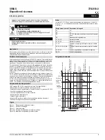
SIRIUS

Safety relay

3TK2810-0

Operating Instructions

English

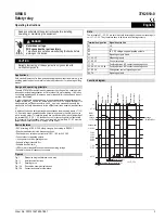
Safe standstill detection for three-phase and single-phase induction motors, e.g. for 

enabling protective doors on machine tools to be released or for activating holding 

brakes.

The safe 3TK2810-0 standstill monitor measures the voltage of the coasting motor 

induced by residual magnetization at 3 terminals of the stator winding. If the induc-

tion voltage approaches 0, this means a motor standstill for the device and the out-

put relay is activated.
In order to be able to adapt the device to the various motors and applications the 

voltage threshold U

an

 can be set, below which the 3TK2810-0 detects standstill. It is 

also possible to set the duration for which U

an

 has to be exceeded to enable the 

standstill to be finally detected and for the output circuit to be enabled (standstill time 

t

s

).

In addition, the device detects strand breaks between the measuring inputs L1 / L2 / 

L3. If a strand break is established the output relay goes into the safe position (as 

with a running motor). This state is stored and can be cleared by (short) jumpering of 

the terminals X2 - X3. X1 - X2: feedback circuit for connecting external contactors 

(NC contacts). If the feedback circuit is not required the terminals X1 - X2 must be 

jumpered as otherwise an error message will be output.

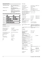
• SIL3 according to IEC 61 508, safety category 4 according to EN 954-1
• Strand break detection in the measuring circuit
• Positively driven safety output contacts: 3 NO, 1 NC for 250 V AC
• 2 semiconductor signaling outputs
• 1 changeover contact signaling output
• Settable voltage threshold U

an

• Settable standstill time t

s

• LEDs for motor standstill, strand break and operating voltage
• Suitable for use with frequency converters

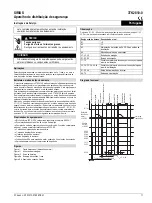
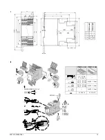
Fig. I

Dimension diagram (dimensions in mm)

Fig. II

Installation instructions

Fig. III

Derating curve

Fig. IVa

Connection example single-phase

Fig. IVb

Connection example three-phase

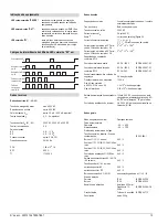
The terminals X1 - X2 - X3 are not electrically isolated with respect to measuring cir-

cuit L1 - L2 - L3. They therefore have to be driven with floating contacts.

Read and understand these instructions before installing, 

operating, or maintaining the equipment. 

 DANGER

Hazardous voltage.

Will cause death or serious injury.

Turn off and lock out all power supplying this device before 

working on this device.

CAUTION

Reliable functioning of the equipment is only ensured with 

certified components.

Applications

Design and operating principle

Device features

Figures

!

Note

Terminal designation Signal description

A1

+/L

A2

–/L

A3

24 V DC voltage supply signaling outputs

A4

Signaling outputs frame

L1, L2, L3

Measuring inputs

X1, X2, X3

Control terminals

11, 12

Positively driven NC contacts enabling circuit

23, 24; 33, 34; 43, 44

Positively driven NO contacts enabling circuit

51, 52, 54

Changeover contact signaling output

64, 74

Signaling outputs

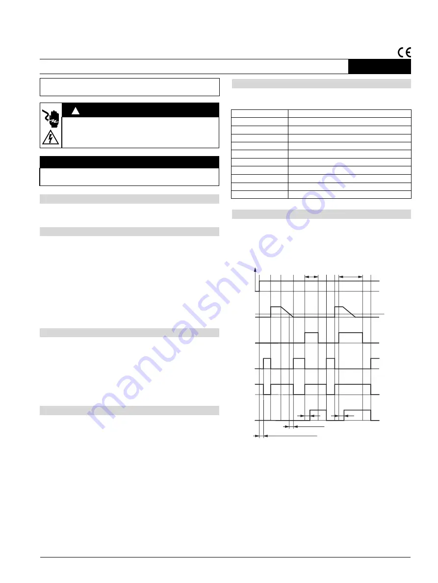
Function diagram

$

$

$$

+

8

6WRS

5HVHW

;

;

5HVHW

;

;

6WUDQGEUHDN

6WUDQGEUHDN

0RWRUVWDQGVWLOOGHWHFWHG

0RWRUFRDVWV

0RWRUFRDVWV

0RWRU2Q

0RWRU2Q

$X[YROWDJH2Q

///

0RWRU
VSHHG
YROWDJH
///

6WUDQGEUHDN

7HVWWLPHGXULQJVZLWFKRQ8

+


9ROWDJH
WKUHVKROG8

DQ

6WDQGVWLOOWLPHW

6

W

(

 V

W

(

W

(

Содержание 3TK2810-0

Страница 1: ...Sicherheitskategorie 4 nach EN 954 1 Aderbrucherkennung im Messkreis zwangsgeführte Sicherheitsausgangskontakte 3 Schließer 1 Öffner für AC 250 V 2 Halbleiter Meldeausgänge 1 Wechsler Meldeausgang einstellbare Spannungsschwelle Uan einstellbare Stillstandszeit ts LED Anzeigen für Motorstillstand Aderbruch und Betriebsspannung geeignet zum Einsatz mit Frequenzumrichtern Bild I Maßbild Maße in mm Bi...

Страница 2: ...aktreihen 5 A 52 52 52 75 A2 Max zulässiger Strom bei 60 C über 3 Kontaktreihen 2 A 22 22 22 12 A2 Schaltvermögen nach AC 15 Schließer Öffner nach DC 13 AC 3 A 230 V AC 2 A 230 V DC 2 A 24 V IEC EN 60 947 5 1 IEC EN 60 947 5 1 IEC EN 60 947 5 1 Empfohlene Absicherung der Sicher heitskontakte 5 A flink Maximale Schalthäufigkeit 1200 h Kontaktlebensdauer bei AC 230 V 5 A cos ϕ 0 5 2 x 10⁵ Schaltbeis...

Страница 3: ...rcuit Positively driven safety output contacts 3 NO 1 NC for 250 V AC 2 semiconductor signaling outputs 1 changeover contact signaling output Settable voltage threshold Uan Settable standstill time ts LEDs for motor standstill strand break and operating voltage Suitable for use with frequency converters Fig I Dimension diagram dimensions in mm Fig II Installation instructions Fig III Derating curv...

Страница 4: ...s 5 A 52 52 52 75 A2 Max permissible current at 60 C over 3 rows of contacts 2 A 22 22 22 12 A2 Switching capacity to 15 AC NO NC to 13 DC 3 A 230 V AC 2 A 230 V AC 2 A 24 V DC IEC EN 60 947 5 1 IEC EN 60 947 5 1 IEC EN 60 947 5 1 Recommended fusing of the safety contacts 5 A quick response Maximum number of switching opera tions 1200 h Contact service life at 230 V AC 5 A cos ϕ 0 5 2 x 10⁵ operat...

Страница 5: ...ties de signalisation à semi conducteur 1 sortie de signalisation à contact inverseur Seuil de tension réglable Uan Temps d immobilisation réglable ts LED pour moteur arrêté rupture de fil et tension de service Convient pour l emploi avec des variateurs de fréquence Fig I Encombrements cotes ein mm Fig II Instructions pour le montage Fig III Courbe de déclassement Fig IVa Exemple de raccordement e...

Страница 6: ... de contacts 5 A 52 52 52 75 A2 Courant max admissible à 60 C sur 3 circuits de contacts 2 A 22 22 22 12 A2 Pouvoir de coupure fermeture en AC 15 Contacts NO Contacts NF en DC 13 CA 3 A 230 V CA 2 A 230 V CC 2 A 24 V CEI EN 60 947 5 1 CEI EN 60 947 5 1 CEI EN 60 947 5 1 Protection recommandée des contacts de sécurité 5 A flink Fréquence de manœuvre maximale 1200 h Endurance des contacts sous 230 V...

Страница 7: ...niobra positiva 3 NA 1 NC para 250 V AC 2 salidas de señalización electrónicas estáticas 1 Contacto conmutado de salida de señalización Umbral de tención ajustable Uan Tiempo de parada ajustable ts LEDs que indican motor parado rotura de hilo y tensión aplicada Apto para funcionar asociado a convertidores de frecuencia Fig I Croquis acotado dimensiones en mm Fig II Instrucciones de montaje Fig III...

Страница 8: ...52 75 A2 ntensidad máx permitida hasta 60 C por 3 circ de contactos 2 A 22 22 22 12 A2 Poder de corte según AC 15 Contactos NA Contactos NC según DC 13 AC 3 A 230 V AC 2 A 230 V DC 2 A 24 V IEC EN 60 947 5 1 IEC EN 60 947 5 1 IEC EN 60 947 5 1 Fusible de protección recomendado de los contactos de seguridad 5 A rápido Frecuencia máx de conmutación 1200 h Vida útil de los contactos con 230 V AC 5 A ...

Страница 9: ...ntatti d uscita sicuri a guida forzata 3 contatti di lavoro 1 di riposo per AC 250 V 2 uscite di segnalazione a semiconduttore 1 uscita di segnalazione con contatto di scambio Soglia di tensione impostabile Uint Tempo di fermo impostabile tf Indicatori LED per fermo motore rottura conduttore e tensione d esercizio Adatto per l impiego con convertitori di frequenza Figura I Disegno quotato dimensio...

Страница 10: ...2 52 52 75 A2 Corrente max ammissibile con 60 C tramite 3 serie di contatti 2 A 22 22 22 12 A2 Potere di manovra secondo AC 15 Contatto di lavoro Contatto di riposo secondo DC 13 AC 3 A 230 V AC 2 A 230 V DC 2 A 24 V IEC EN 60 947 5 1 IEC EN 60 947 5 1 IEC EN 60 947 5 1 Protezione consigliata dei contatti di sicurezza 5 A rapido Massima frequenza di manovra 1200 h Durata dei contatti con AC 230 V ...

Страница 11: ...segurança de condução forçada 3 contatos normalmente abertos 1 contato normalmente fechado para 250 V AC o 2 saídas de sinalização de semicondutores o 1 saída de sinalização de inversor o Limiar de tensão Uan ajustável o Tempo de parada ts ajustável o Indicação de LEDs para parada de motor quebra de fios e tensão de operação o Apropriado para o uso com conversores de freqüência Figura I Figura dim...

Страница 12: ...e 3 fileiras de contatos 5 A 52 52 52 75 A2 Corrente máx permitida a 60 C atra vés de 3 fileiras de contatos 2 A 22 22 22 12 A2 Capacidade de comutação conforme AC 15 Contato normalmente aberto Contato normalmente fechado conforme DC 13 AC 3 A 230 V AC 2 A 230 V DC 2 A 24 V IEC EN 60 947 5 1 IEC EN 60 947 5 1 IEC EN 60 947 5 1 Fusível recomendado dos contatos de segurança 5 A de ação rápida Freqüê...

Страница 13: ...4 4 d 105 9 107 7 I 2 1 3 5 4 DIN ISO 2380 1A 0 5 x 3 A B C D A B C D Kodiert Coded Codé Cifrado Codificato Codificado a b c d 3TK2810 0 A01 3TK2810 0 A02 5 6 mm PZ2 0 8 1 2 Nm 7 10 3 lb in 1 x 0 5 4 0 mm 2 x 0 5 2 5 mm 2 x 0 25 1 5 mm 2 x 0 5 1 5 mm 1 x 0 5 2 5 mm 2 x 0 25 1 5 mm 2 x 0 25 1 5 mm AWG 2 x 20 to 14 2 x 24 to 16 10 10 10 II 3RP1903 ...

Страница 14: ...tance Telephone 49 0 911 895 5900 8 17 CET Fax 49 0 911 895 5907 E mail technical assistance siemens com Internet www siemens de lowvoltage technical assistance Technical Support Telephone 49 0 180 50 50 222 III 7 IVa IVb 1 3 4 4 7 0 a 1 4 4 0RWRUVFK W 0RWRU FRQWDFWRU RQWDFWHXU PRWHXU RQWDFWRU GH PRWRU RQWDWWRUH PRWRUH RQWDWRU GH PRWRU 3 4 4 7 0 a 1 4 4 0RWRUVFK W 0RWRU FRQWDFWRU RQWDFWHXU PRWHXU ...

Отзывы: