background image

Settings in BIOS Setup

The 

BIOS Setup

 menu allows you to set your hardware configuration and system

functions. In addition, the 

BIOS Setup

 displays technical information on the PC's

configuration.

Pressing the function key  

F1

  provides help information on each entry field.

When it is supplied, the PC is set to factory default settings which you can alter in
the 

BIOS Setup

 menus. Any changes you make take effect as soon as you save the

settings and quit the 

BIOS Setup

.

The Operating Manual describes how to call the setup menu and change menu
entries.

You can select the following settings in the 

BIOS Setup

:

Main

 - system functions

Advanced

 - advanced system configuration

Security

 - security features

Power

 - power-management features

Exit

 - save and quit

The various menus are described below with all setting options. Since the

i

setting options depend on your PC's hardware configuration, some of them
may not be offered in the BIOS setup.

System settings - Main menu

In the 

Main

 menu


you can set up the following:

–  Time (in the field marked 

System Time

)

–  Date (in the field marked 

System Date

)

–  Floppy disk drive (in the field marked 

Diskette A

 or 

Diskette B

)

–  Hard disk drive (in the submenus of 

Hard Disk

)

–  System boot (in the submenus of 

Boot Options

)

–  Display device (in the field marked 

Video Display

)

A26361-D842-Z120-6-7619


7

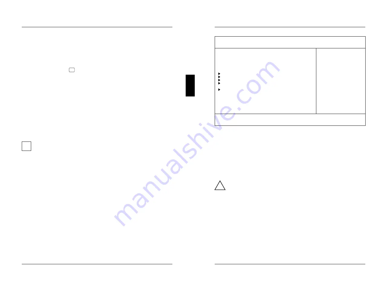
Settings in BIOS Setup Main

       Phoenix BIOS Setup Copyright 1985-94 Phoenix Technologies Ltd.
  

Main

    Advanced    Security    Power    Exit

                                                      Item Specific Help
  System Time:         [07:42:19]                   –––––––––––––––––––––––
  System Date:         [02/28/1995]

  Diskette A:          [1.4M]
  Diskette B:          [None]

 Hard Disk 1:         540 Mbyte
 Hard Disk 2:         None
 Hard Disk 3:         None
 Hard Disk 4:         None

 Boot Options

  Video Display:       [EGA/VGA]

  Base Memory:            640K
  Extended Memory:         15M

F1  Help    

↑↓

 Select Item    -/+   Change Values      F9 Setup Defaults

ESC Exit    

←→

 Select Menu   Enter Execute Command    F7 Previous Values

Example for

 Main

 menu

Time and Date - System Time / System Date

The 

System Time

 field and the 

System Date

 field show the time and date respectively

according to the PC. The time is shown in the format

 hours:minutes:seconds

 and the

date is shown in the format 

month/day/year

. You can move the cursor within the

Time and Date fields (e.g. from hour to minute) using the tabulator key.

!

If the settings in the 

System Time

 and 

System Date

 fields are frequently wrong

when you power up the computer, the lithium battery is dead. Change the
battery as described in "Add-on modules - Replacing the lithium battery").

Floppy disk drive - Diskette A / Diskette B

These two fields are used to specify the type of floppy disk drive installed.

360K, 720K, 1.2M, 1.4M

2.8M

The entry depends on the floppy disk drive installed.
(Default entry 

Diskette A

:

 1.4M

)

None


A floppy disk drive is not installed.
(Default entry 

Diskette B

:

 None

)

8


A26361-D842-Z120-6-7619

Содержание D842

Страница 1: ...sido impreso sobre papel reciclado Questo manuale è stato stampato su carta da riciclaggio Denna handbok är tryckt på recyclingpapper Dit handboek werd op recycling papier gedrukt Herausgegeben von Published by Siemens Nixdorf Informationssysteme AG D 33094 Paderborn D 81730 München Bestell Nr Order No A26361 D842 Z120 1 7619 Printed in the Federal Republic of Germany AG 0496 04 96 A26361 D842 Z12...

Страница 2: ...quoting Please contact the order number of the manual one of our IT Service Shops your sales partner Siemens Nixdorf Informationssysteme AG your sales office User Documentation Department BS2000 QM2 Otto Hahn Ring 6 You will find the addresses of the 81730 München Germany IT Service Shops in the enclosed warranty booklet Fax 49 89 6 36 4 04 43 ...

Страница 3: ... Adaptec Inc Intel and Pentium are registered trademarks and OverDrive is a trademark of Intel Corporation USA Microsoft MS MS DOS Windows and Windows 95 are registered trademarks of Microsoft Corporation PS 2 and OS 2 Warp are registered trademarks of International Business Machines Inc SCO and SCO Unix are registered trademarks of Santa Cruz Operation All other trademarks referenced are the trad...

Страница 4: ...ts Setting energy saving functions Power menu 30 Enabling the APM Interface APM 30 Extent of energy saving functions Power Management Mode 31 Standby mode Standby Timeout 32 Hard disk energy saving functions Hard Disk Timeout 32 Processor clock Standby CPU Speed 32 Wakeup Event Defininig system activities 33 Exiting BIOS Setup Exit menu 33 Save Changes Exit 33 Discard Changes Exit 33 Get Default V...

Страница 5: ...CP mode 50 Serial interface 51 PS 2 mouse port 52 PS 2 keyboard port 52 Interrupt Request Levels and DMA channels 53 Error messages 55 Messages d erreur 57 Mensajes de error 59 Messagi di errore 61 Felmeddelanden 63 Foutmeldingen 65 Index 67 A26361 D842 Z120 6 7619 ...

Страница 6: ...ext and names of chapters A26361 D842 Z120 6 7619 1 Introduction Features 64 bit microprocessor Pentium with 16 Kbyte internal cache first level cache 8 Kbyte data cache 8 Kbyte address cache or OverDrive processor for Pentium Math coprocessor integrated in processor Memory configuration on system board 8 Mbyte to 128 Mbyte Second level cache on the system board 256 Kbyte PCI bus Disk controller c...

Страница 7: ...are using an external monitor controller you will find details of supported screen resolutions in the Operating Manual or Technical Manual supplied with the controller A26361 D842 Z120 6 7619 3 Introduction You can use the REFRATE program under Windows 95 the WDSETUP program under MS Windows or the SET VGA program under MS DOS to set the screen resolution Detailed information is provided in the co...

Страница 8: ...u Vaihda paristo ainoastaan laitevalmistajan suosittelemaan tyyppiin Hävitä käytetty paristo valmistajan ohjeiden mukaisesti A26361 D842 Z120 6 7619 5 Important Notes Modules with electrostatic sensitive devices ESD may be identified by labels When you handle modules fitted with ESDs you must observe the following points under all circumstances When you handle modules fitted with ESDs you must alw...

Страница 9: ...e field marked Video Display A26361 D842 Z120 6 7619 7 Settings in BIOS Setup Main Phoenix BIOS Setup Copyright 1985 94 Phoenix Technologies Ltd Main Advanced Security Power Exit Item Specific Help System Time 07 42 19 System Date 02 28 1995 Diskette A 1 4M Diskette B None Hard Disk 1 540 Mbyte Hard Disk 2 None Hard Disk 3 None Hard Disk 4 None Boot Options Video Display EGA VGA Base Memory 640K E...

Страница 10: ... Z120 6 7619 9 Settings in BIOS Setup Main Only if you have installed a new IDE hard disk drive you should mark the Autotype Hard Disk field and press Enter This has the effect of setting the optimum values for the IDE hard disk drive You can change these values if you set the Type field to User Type Hard Disk Type This field is used to specify the type of hard disk drive installed None You cannot...

Страница 11: ...wing the disk s full capacity to be used If the hard disk does not support LBA its parameters are not translated Disabled The BIOS uses the hard disk parameters and supports a maximum capacity of 528 Mbytes PIO Mode Transfer rate The PIO Programmed Input Output Mode defines the transfer rate of the IDE hard disk drive Standard 0 8 Mbyte s to 2 Mbyte s default entry Fast PIO 1 2 Mbyte s to 4 Mbyte ...

Страница 12: ...p Advanced Making advanced system settings Advanced menu Change the default settings only for special applications Incorrect settings can cause malfunctions You can make the following system settings in the Advanced menu Internal cache and second level cache in the Cache Memory submenu Copy BIOS sections to the RAM in the Shadow Memory submenu Interfaces and controllers in the Peripheral Configura...

Страница 13: ... disabled All cache related settings are then without effect A26361 D842 Z120 6 7619 15 Settings in BIOS Setup Advanced Cache Mode Condition The Cache field must be set to Intern Only or Intern And Extern Cache Mode sets the mode in which the CPU uses the cache In write back mode the CPU writes information to the cache and the information is only written to main memory if necessary Memory and cach...

Страница 14: ...Z120 6 7619 17 Settings in BIOS Setup Advanced Shadow Memory Regions ROM areas Shadow Memory Regions allows you to copy ROM areas to fast RAM Copying ROM areas to fast RAM increases system performance Enabled The ROM area is copied to fast RAM Disabled The ROM area is not copied to fast RAM default entry Peripheral Configuration Interfaces and controllers calls the submenu in which you can set the...

Страница 15: ...pports the ECP Enhanced Capability Port transfer mode Diskette Controller This field is used to enable and disable the built in floppy disk controller on the system board Enabled The floppy disk controller is enabled IRQ 6 is used default entry Disabled The floppy disk controller is disabled IRQ 6 is free A26361 D842 Z120 6 7619 19 Settings in BIOS Setup Advanced Hard Disk Controller This field al...

Страница 16: ... any PCI interrupts If you use a setting other than Auto the Plug Play functionality of the system BIOS for PCI boards is deactivated The PCI interrupts INTA and INTB are assigned as follows PCI slot 1 INTA PCI slot 2 INTB Auto The PCI interrupts are assigned automatically in accordance with the Plug Play guidelines default entry Disabled No PCI interrupt is used for the PCI board in the assigned ...

Страница 17: ... Exit Select Menu Enter Execute Command F7 Previous Values Example for submenu Advanced System Configuration A26361 D842 Z120 6 7619 23 Settings in BIOS Setup Advanced Video Subsystem Monitor controller defines settings for the monitor controller If you are using your own monitor controller and are encountering problems this setting may be the cause Auto default entry 3C3h 46E8h further possible s...

Страница 18: ...ecurity features in the Security menu Protecting BIOS Setup in the field marked Set Setup Password Protecting BIOS of add on modules in the field marked Set Setup Lock Protecting system boots in the field marked Set System Password Locking input devices in the field marked System Password Mode Prevention of system boots from floppy disk in the field marked System Load Virus Warning in the field ma...

Страница 19: ... system is booted and the keyboard and mouse are locked The system password unlocks the keyboard and mouse No prompt is displayed A26361 D842 Z120 6 7619 27 Settings in BIOS Setup Security System Load This field specifies the drive from which the operating system can be loaded Standard The operating system can be loaded from floppy disk or hard disk default entry Diskette Lock The operating system...

Страница 20: ...ting energy saving functions Power menu Programs for power management e g POWER EXE can change the settings for the energy saving functions You can set the following functions in the Power menu Enabling of APM interface in the Advanced Power Management field Extent of energy saving functions in the Power Management Mode field Standby mode in the Standby Timeout field Hard disk energy saving functi...

Страница 21: ... with the entry in the Standby CPU Speed field The next wakeup event terminates standby mode again 2 min 5 min 10 min 15 min 30 min Default entry 15 min Disabled The PC does not switch to standby mode Hard disk energy saving functions Hard Disk Timeout Requirement the Power Management Mode must be set to Customize This field defines the amount of time without system activity before the motor of th...

Страница 22: ...es F1 Help Select Item Change Values F9 Setup Defaults ESC Exit Select Menu Enter Execute Command F7 Previous Values Example for submenu Exit Save Changes Exit saves the settings you have made and exits BIOS Setup Discard Changes Exit exits BIOS Setup without saving the new settings A26361 D842 Z120 6 7619 33 Settings in BIOS Setup Power Exit Get Default Values reverts all settings to the default ...

Страница 23: ...u must ensure that the Flash Write field in the BIOS Setup Security menu is set to Enabled If you wish to update your system BIOS please consult our customer service ON System BIOS is write protected BIOS updating disabled OPEN BIOS updating is enabled default setting Write protection for floppy disk drive Switch 4 Switch 4 is used to define whether floppy disks can be written or deleted in the fl...

Страница 24: ...emove memory modules you may have to remove the disk drive mount see your PC s technical manual You may only use fast memory modules access time 70ns or less You must always add memory modules in pairs In other words you fit the first pair to bank 0 and the second pair in bank 1 Pairs of memory modules must have the same capacity and the same access time A26361 D842 Z120 6 7619 37 Add on modules I...

Страница 25: ...rted not inserted Make sure that the system board near the processor is marked S26361 D842 B Note that system boards marked S26361 D842 A may only be operated with 75 90 100 MH processors If in doubt contact our field service department A26361 D842 Z120 6 7619 39 Add on modules If the power consumption of the new processor is different from that of the i old processor you must also exchange the vo...

Страница 26: ...P under MS Windows or REFRATE under Windows 95 A26361 D842 Z120 6 7619 41 Add on modules Replacing the lithium battery Please note the information provided in the chapter Important notes in this manual Incorrect replacement of the lithium battery may lead to a risk of explosion The lithium battery must be replaced with an identical battery or a battery type recommended by the manufacturer CR2032 D...

Страница 27: ... 3 3 V A26361 D842 Z120 6 7619 43 Interface pinouts and interrupts Connector for soft off power supply 1 3 Pin Meaning 1 5 V auxiliary voltage 2 Power Supply ON 3 0 V Connector for soft off power switch 1 2 Pin Meaning 1 5 V auxiliary voltage 2 Power switch input Connector for external loudspeaker 1 4 Pin Meaning 1 loudspeaker 2 coded 3 not used 4 5 V Connector for remote power on 1 2 Pin Meaning ...

Страница 28: ...ard disk LED 3 SCSI hard disk LED 4 not used A26361 D842 Z120 6 7619 45 Interface pinouts and interrupts Connector for external monitor controller VESA VGA pass through 26 1 2 Pin Meaning Pin Meaning 1 0 V 14 Data 6 2 Data 0 15 0 V 3 0 V 16 Data 7 4 Data 1 17 0 V 5 0 V 18 Clock 6 Data 2 19 0 V 7 not used 20 Blanking 8 Data 3 21 0 V 9 not used 22 Horizontal Sync 10 Data 4 23 not used 11 not used 24...

Страница 29: ...ta 2 40 Host Data 7 16 Image Line Sync 41 free 17 Image Data 3 42 free 18 0 V 43 free 19 Image Data 4 44 free 20 Image Data Ready 45 free 21 Image Data 5 46 free 22 0 V 47 free 23 Image Data 6 48 free 24 Odd Image Data 49 0 V 25 Image Data 7 50 0 V A26361 D842 Z120 6 7619 47 Interface pinouts and interrupts Connector for monitor 1 5 6 10 11 15 Pin Meaning Pin Meaning 1 Red 9 keyed no pin 2 Green 1...

Страница 30: ...essage 2 9 Data Lines 0 7 Data lines 0 7 10 ACKNOWLEDGE Data acknowledgement 11 BUSY Not ready to receive 12 PE End of paper 13 SELECT Device selection 14 AUTO Automatic new line 15 ERROR Device error 16 INIT Reset initialize 17 SELECT IN Printer selection 18 25 GROUND Ground A26361 D842 Z120 6 7619 49 Interface pinouts and interrupts Pinout in EPP mode Pin Signal Signal direction 1 Write Output 2...

Страница 31: ...Send 9 Ri Ring Indicator A26361 D842 Z120 6 7619 51 Interface pinouts and interrupts PS 2 mouse port 1 4 2 3 5 6 Pin Signal 1 Mouse data 2 not used 3 0 V 4 5 V 5 Mouse clock 6 not used PS 2 keyboard port The entries in parentheses are effective if the jumper X507 is inserted on 2 4 and 3 5 1 4 2 3 5 6 Pin Meaning 1 Keyboard data 2 not used Mouse data 3 0 V 4 5 V 5 Keyboard clock 6 not used or powe...

Страница 32: ... 1 COM1 COM3 IRQ5 free or parallel interface LPT2 IRQ6 floppy disk controller IRQ7 parallel interface LPT1 LPT3 IRQ8 real time clock interrupt IRQ9 free or VGA controller IRQ10 free IRQ11 free IRQ12 mouse IRQ13 math coprocessor IRQ14 IDE disk controller connector 1 IRQ15 IDE disk controller connector 2 DMA channels DMA0 free DMA1 free DMA2 floppy disk controller DMA3 free ECP mode DMA4 DMA channel...

Страница 33: ...N SETUP Correct the entry for the monitor type in the Main menu of the BIOS Setup Operating system not found Check the entries for the hard disk drive and the floppy disk drive in the Main menu of the BIOS Setup A26361 D842 Z120 6 7619 55 Error messages Parity Check 1 Parity Check 2 Switch the PC off and on again If the message is still displayed please contact your sales office or customer servic...

Страница 34: ... does not match CMOS RUN SETUP Entrez dans le menu Main du BIOS setup et paramétrez correctement l entrée correspondant au type d écran A26361 D842 Z120 6 7619 57 Messages d erreur Operating system not found Vérifiez dans le menu Main du BIOS setup les entrées correspondant au lecteur de disque dur et au lecteur de disquettes Parity Check 1 Parity Check 2 Redémarrez votre PC Si le message réappara...

Страница 35: ...e does not match CMOS RUN SETUP Defina correctamente en el menú principal del BIOS Setup el registro para el tipo de pantalla A26361 D842 Z120 6 7619 59 Mensajes de error Operating system not found Compruebe en el menú principal del BIOS Setup los registros de la unidad de disco duro y de la unidad de disquete Parity Check 1 Parity Check 2 Arranque de nuevo el PC Si sigue visualizándose este mensa...

Страница 36: ...a collegata correttamente Monitor type does not match CMOS RUN SETUP Impostate nel BIOS Setup del menu principale il valore corretto per il tipo di monitor Operating system not found Controllate nel BIOS Setup del menu principale i valori indicati per il drive per il disco rigido e per il drive per dischetti A26361 D842 Z120 6 7619 61 Messagi di errore Parity Check 1 Parity Check 2 Riavviate nuova...

Страница 37: ...ordet är korrekt anslutet Monitor type does not match CMOS run SETUP Korrigera inställningarna för bildskärmtypen i menyn Main i BIOS Setup menyn Operating system not found Kontrollera inställningarna för hårddisken och diskettenheten i menyn Main i BIOS Setup menyn A26361 D842 Z120 6 7619 63 Felmeddelanden Parity Check 1 Parity Check 2 Starta upp PCn på nytt Om meddelandet fortfarande visas bör d...

Страница 38: ...oten Keyboard error nn Laat de toets van het toetsenbord los nn is de hexadecimale code voor de toets A26361 D842 Z120 6 7619 65 Foutmeldingen Monitor type does not match CMOS RUN SETUP Stel in de setup van het BIOS in het menu Main het monitortype op de juiste wijze in Operating system not found Controleer in de setup van het BIOS in het menu Main de instellingen van de harde schijf en het disket...

Страница 39: ...4 Error messages 55 Connector remote power on 44 ESD modules 6 Connector soft off power supply 44 Exiting BIOS Setup 33 Connector VESA VGA pass through Expansion second level cache 34 46 Explanation of fonts 1 Connectors 3 Explanation of symbols 1 Controller monitor 24 Extended Capabilities Port mode Controller floppy disk drive 19 parallel interface 50 Controller setting 18 Extended Memory 13 Cou...

Страница 40: ... 28 A26361 D842 Z120 6 7619 69 Index Operating system starting 27 Pinout serial interface 51 Parallel interface configuring 19 Pinout soft off power supply 44 Parallel interface ECP mode 50 Pinout soft off power switch 44 Parallel interface EPP mode 50 Pinout VESA VGA pass through 46 Parallel interface pinout 49 PIO Mode 11 Parallel interface SPP mode 49 Plug Play settings 24 Parallel Mode 19 Plug...

Страница 41: ...2 Setting mouse controller 20 SPP modes parallel interface 49 Setting PCI slot 21 23 Standard Parallel Port mode 49 Setting peripherals 18 Standby function clock speed 32 Setting Plug Play 24 Standby mode setting 32 Setting second level cache memory Standby CPU Speed 32 34 Standby Timeout 32 Setting self test 13 Starting operating system 27 Setting serial interfaces 18 Switch BIOS recovery 35 Sett...

Отзывы: