Siegenia AEROLIFE Скачать руководство пользователя страница 21

Original operating instructions AEROLIFE

08.2016

21

Liability

Intended use

Any use of this product that is not in accordance with its intended use, or any adaptation of or modification to the product 
and its associated components for which our express consent has not been obtained, is strictly prohibited. We accept no 
liability whatsoever for any material losses or injury to people caused by failure to comply with this stipulation.

Product liability

Our products are guaranteed – subject to correct installation and proper use – for a period of one year from the date of 
receipt by a company (according to our general terms and conditions) or as otherwise agreed, and for a period of two years 
for end consumers, in accordance with statutory provisions. As part of our ongoing improvements, we reserve the right to 
replace individual components or entire products. Consequential losses resulting from defects are excluded from the 
warranty within the limits of the law. The warranty shall become void if modifications that are not authorised by us or have not 
been described in this documentation are performed on the product and/or individual components, or if the product and/or 
individual components is/are dismantled or partly dismantled, and the defect is due to the changes made.

Exclusion of liability

The product and its components are subject to stringent quality controls. As a result, they function reliably and safely when 
used correctly. Our liability for consequential losses and/or claims for damages is excluded, except in the case of wilful 
misconduct or gross negligence, or where we are responsible for injury to life, limb or health. Strict liability under the German 
Product Liability Act (Produkthaftungsgesetz) remains unaffected. Liability for the culpable violation of significant contractual 
obligations also remains unaffected; liability in this case is limited to losses that are specific to the contract and that could 
have been foreseen. The above regulations do not imply a change in the burden of proof to the detriment of the consumer.

Environmental protection

Although our products do not fall within the scope of the German Electrical and Electronic Equipment Act, SIEGENIA will 
continue to meet the requirements of this Act and will endeavour to completely eliminate the use of substances that are 
hazardous to the environment as soon as this becomes technically feasible. Electrical products should not be disposed of as 
household waste.

Feedback on documentation

We welcome your comments and suggestions on how to improve our documentation. Please email your comments to 
[email protected].

Содержание AEROLIFE

Страница 1: ...AERO Wall mounted ventilator with heat recovery AEROLIFE Window systems Door systems Comfort systems ORIGINAL OPERATING INSTRUCTIONS ...

Страница 2: ......

Страница 3: ...umentation 4 Intended use 4 Safety notices 5 Scope of delivery 5 Installation 6 Unit description 12 Function 14 Commissioning 15 Operation 15 Care and maintenance 16 Accessories 18 Technical data 19 Dimensions 20 Liability 21 Feedback on documentation 21 EU Declaration of Conformity 22 ...

Страница 4: ...cations The AEROLIFE may only be mounted in a vertical position The unit may not be installed on diagonal surfaces e g walls ceilings If the unit is to be used in a room with a heating unit that draws air from the room prior authorisation must be obtained from the proper authorities such as the officially appointed district chimney sweep Only operate and or store the AEROLIFE at temperatures betwe...

Страница 5: ...d it must be replaced by SIEGENIA the company s customer service department or similarly qualified personnel in order to prevent personal injury or damage to property Only a qualified electrician may perform any work on the 230 V AC mains power supply that is required in order to connect the device All pole safety isolation is required if the customer is fitting the mains cable Current local regul...

Страница 6: ...ce must be level plastered min 350 mm 437 mm 75 mm 78 mm 462 mm Step 2 Marking drill holes With in wall mounting and permanent electrical connection 1 Cut out the drilling template along the dotted line for in wall mounting 2 Cut out an opening in the drilling template at the point marked with a cross and draw the end of the cable through the opening 3 Align the drilling template with a spirit lev...

Страница 7: ...les 1 Drill core hole ø 120 3 Using a hammer drill at an angle of approx 2 to 5 drill a hole through to the outside wall ø120 3 2 Drill the four marked mounting holes all drill holes ø 8 mm at least 45 mm deep 3 Insert four S8 dowels included in delivery into the drilled holes Note depending on the type of wall e g plasterboard suitable dowels may need to be provided by the customer for inserting ...

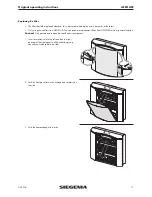
Страница 8: ...ntil the pipe is firmly seated 2 Fix the transition point with the adhesive tape included in the delivery Pipe and socket piece must be firmly connected Step 6 Removing the front panel 1 Insert screwdriver into the left and then the right opening of the front panel until the underlying snap connection is released at both sides 2 Fold the front panel forwards unhinge and set down on the side ...

Страница 9: ...nnecting cable in the cable duct in a clockwise or anticlockwise direction Note The cable must be neatly laid in the cable duct to prevent it from being squeezed or carried through during the installation a b Step 8 Screwing the ventilation unit to the wall 1 Lift the ventilation unit and push the attached pipe through the wall opening 2 Press the ventilation unit firmly against the wall and faste...

Страница 10: ... top breakthrough on the terminal box Step 10 Inserting the blower units 1 Insert the top and bottom blower unit and press slightly against the contacts Note The blower units are retained in this position after the front panel has been mounted Yellow round label Spring loaded PVC pin Step 11 Inserting the foam strips 1 Press the foam strips into the hollow cavity between the casing and the top blo...

Страница 11: ...the display to test the function of the ventilation unit 5 After the successful test switch off the device Note Check the correct seating of the front panel if the ventilation unit is not functioning Step 13 Mounting the weather grille 1 Apply permanently elastic sealing compound to the outer edge of the pipe and mount the weather grille 2 Press the weather grille firmly against the pipe Two clamp...

Страница 12: ...instructions 08 2016 Unit description AEROLIFE 1 Housing base 2 Display 3 Button 4 Housing frame 5 Front panel 6 Air inlet and outlet with closing caps 7 Cable duct 8 Socket piece 9 Mains cable with Euro plug 5 4 1 2 3 6 1 4 6 8 9 7 ...

Страница 13: ...ir flow level three possible levels Ventilation Operation of blower units Filter replacement required Note The filter is monitored by the current consumption of the unit If the unit is continually operated at air flow level 1 or 2 the AEROLIFE processor will switch to air flow level 5 for approx two minutes every 8 hours in order to check the filter for measuring reasons The unit then automaticall...

Страница 14: ...yed into the room through the two bottom air outlets b a a b b Ventilation elements The heat exchanger absorbs part of the heat in the discharged room air and heats up the fresh air supplied You can fold out the heat exchanger to exchange the filter unit in the heat exchanger The filter unit consists of a cassette filter filter grade F7 which filters over 97 of the pollen from the fresh air and a ...

Страница 15: ...y terminals supply 230 V AC even when the front panel has been removed Do not remove the cover of the connecting clamps behind the top housing unit Following the successful installation and electrical connection of the AEROLIFE the unit can be commissioned The Euro plug of the mains cable must be properly connected to the 230 V AC mains power supply via a power socket If the unit has been permanen...

Страница 16: ...onnect the unit from the mains power supply Switch off all poles of the feeder on units with permanent connection to 230 V AC mains power supply The fuses may need to be removed Cleaning Important When cleaning the AEROLIFE do not allow liquids to get inside the unit Never use cleaning agents that are aggressive or contain solvents or sharp edged objects as these may damage the surfaces of the cas...

Страница 17: ...rom SIEGENIA You can purchase replacement filters from SIEGENIA or from specialist retailers Caution Only activate and remove the specified unit components 1 Insert a screwdriver into the left and then the right opening of the front panel until the underlying snap connection is released at both sides 2 Fold the front panel forwards unhinge and set down on the side 3 Fold the heat exchanger forward...

Страница 18: ...wo aluminium edges a b The upper edge of the cardboard strip must close under the top aluminium edge The bottom edge of the fleece filter must be pressed behind the bottom aluminium edge c 6 Reassemble the AEROLIFE in the reverse order Note Check the correct seating of the front panel if the AEROLIFE does not function at once after the filter exchange a b c Accessories Material description Materia...

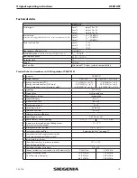
Страница 19: ... 14 9 kWh m a E 46 3 kWh m a A 7 8 kWh m a F 28 9 kWh m a B 65 7 kWh m a A d typology RVU BVU e type of drive multi speed drive f heat recovery system recuperative g thermal efficiency 53 8 h maximum flow rate 60 m h i electric power input 32 W j sound power level 42 dB A k reference flow rate 43 m h l reference pressure difference m specific power input 0 51 W m h n control factor control typolog...

Страница 20: ...20 AEROLIFE Original operating instructions 08 2016 Dimensions ...

Страница 21: ...antled or partly dismantled and the defect is due to the changes made Exclusion of liability The product and its components are subject to stringent quality controls As a result they function reliably and safely when used correctly Our liability for consequential losses and or claims for damages is excluded except in the case of wilful misconduct or gross negligence or where we are responsible for...

Страница 22: ...cuments EN 55014 1 2006 EN 55014 2 1997 A1 EN 61000 3 2 2006 EN 61000 3 3 1995 A1 A2 EN 60335 1 2010 EN 60335 2 80 2003 A1 2004 EN 62233 2008 EN 62233 Br 1 2008 EN 62233 2008 11 EN ISO 12100 2010 RoHS 2011 65 EU This declaration is based on test reports from EMC TestHaus Dr Schreiber GmbH Test protocol 14 317 Siegen 2014 11 03 S Bauerdick site manager The technical documents will be provided by SI...

Страница 23: ......
Страница 24: ... 85 4861080 China Phone 86 316 5998198 France Phone 33 3 89618131 Germany Phone 49 271 39310 Great Britain Phone 44 2476 622000 Hungary Phone 36 76 500810 Italy Phone 39 02 9353601 Poland Phone 48 77 4477700 Russia Phone 7 495 7211762 South Korea Phone 82 31 7985590 Switzerland Phone 41 33 3461010 Turkey Phone 90 216 5934151 Ukraine Phone 380 44 4637979 You can find address details for our interna...

Отзывы: