


44/74/94
35
14
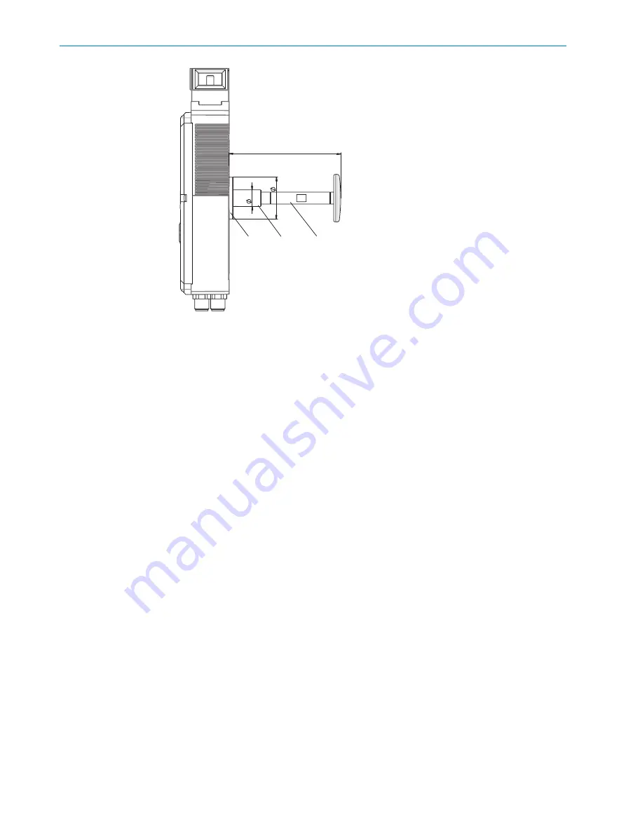
Figure 9: Escape release shaft
1
Escape release flange
2
Escape release shaft
3
Extension spacer
4.4
Integration in the electrical control system
Switch-on commands that put the machine in a dangerous state may only be activated
when the protective device is closed and the locking device is locked. The locking
device may only be unlocked when the dangerous state has ended. Depending on the
safety concept, the signal is analyzed by safety relays or a safety controller, for example.
The connected controller and all devices responsible for safety must comply with the
required performance level and the required category (for example according to
ISO 13849-1).
The overall concept of the control system in which the safety locking device is inte‐
grated must be validated in accordance with ISO 13849-2.
4.4.1
Locking function
Prerequisites
•
A shared power supply is used for the control system and for the locking solenoids
of the safety locking device.
•
A clocked power supply is
not
used.
•
When connecting the locking solenoids to the output of a controller, this output
must supply sufficient current.
The activation of the locking solenoids of the safety locking device changes depending
on the locking principle.
Power to release principle
•
Locking the locking device: Close the protective device, no voltage on the magnet
•
Unlocking the locking device: Apply voltage to magnet
If voltage is interrupted at the magnet, the locking device remains locked and the pro‐
tective device cannot be opened immediately.
PROJECT PLANNING
4
8023119/15LY/2019-10-28 | SICK
O P E R A T I N G I N S T R U C T I O N S | TR110 Lock
17
Subject to change without notice


