background image

Image: E

5

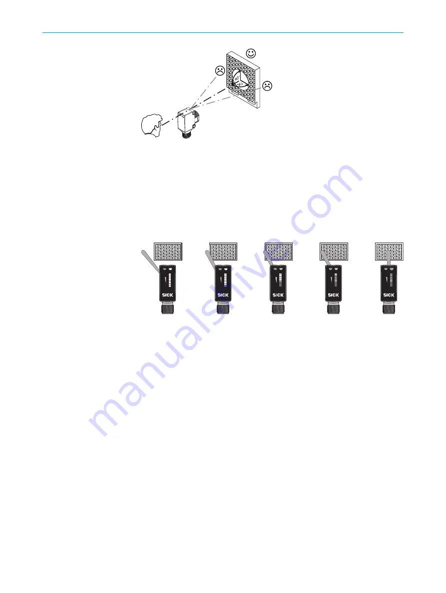
Сенсор без регулировки: сенсор настроен с завода и готов к эксплуатации.
После проведенного выравнивания поместите в траекторию луча
непрозрачный предмет. Для проверки функционирования воспользуйтесь
графиками C и G. Если характер поведения коммутирующего выхода не
соответствует графику С, проверить условия применения. См. раздел
"Диагностика неисправностей".

0 %

100 %

0 %

100 %

0 %

100 %

0 %

100 %

0 %

100 %

Image: F

Сенсор с потенциометром:
С помощью потенциометра (тип: 270°) регулируется чувствительность.
Вращение вправо: увеличение функционального резерва, вращение влево:
уменьшение функционального резерва. Рекомендуется устанавливать
потенциометр на Maximal. На деполяризующих поверхностях, крайне малых
или прозрачных объектах можно рекомендовать использование уменьшенного
функционального резерва.
Сенсор настроен и готов к эксплуатации. Для проверки функционирования
воспользуйтесь графиками C и G. Если характер поведения коммутирующего
выхода не соответствует графику С, проверить условия применения. См. раздел
"Диагностика неисправностей".

75 

ВВОД В ЭКСПЛУАТАЦИЮ

60

8017856.YMH6

 | SICK


Subject 

to change without notice

Содержание SureSense HL18L Series

Страница 1: ...O P E R A T I N G I N S T R U C T I O N SureSense HL18L Cylindrical photoelectric sensors en de fr it pt es zh ru 8017856 YMH6 SICK AG Erwin Sick Strasse 1 D 79183 Waldkirch ...

Страница 2: ...ation or incorrect use can lead to hazardous exposure due to laser radiation 2 Correct use The HL18L is an opto electronic photoelectric retro reflective sensor referred to as sensor in the following for the optical non contact detection of objects A reflector is required for this product to function If the product is used for any other purpose or mo dified in any way any warranty claim against SI...

Страница 3: ...ector with each other Note the sensor s maximum permissible tightening torque of 0 56 Nm 3 The sensors must be connected in a voltage free state Uv 0 V The information in the graphics B must be observed depending on the connection type Male connector connection pin assignment Cable core color L Q1 Q2 brn wht M blu blk 1 4 2 3 Image B x4xxxx x3xxxx L Q2 M brn wht blu blk Q1 Image B 2 x1xxxx L M Q b...

Страница 4: ...r are comple tely clear Optimized alignment can be achieved and verified by using the signal strength light bar located on the back cover of the sensor The LEDs on the light bar will illumina te corresponding to the signal strength of light received by the sensor When no or only red LEDs are illuminated the sensor is receiving no or too little signal to switch the output The first yellow LED will ...

Страница 5: ...age G 5 Additional functions Alarm output The sensor HL18L features a pre failure notification output Q2 in connection diagram B if the alarm option is selected which issues a notification if the signal strength of the light being received is not sufficient Possible causes Sensor or reflector is contaminated sensor is out of alignment In the good state LOW UV V if excessively contaminated HIGH UV ...

Страница 6: ... all electrical connecti ons cables and plug connecti ons Green LED does not light up Green LED does not light up Voltage interruptions Voltage interruptions Ensure there is a stable power supply without interruptions Ensure there is a stable power supply without interruptions Green LED does not light up Green LED does not light up Sensor is faulty Sensor is faulty If the power supply is OK re pla...

Страница 7: ...ee graphic H Dis tance between the sensor and the reflector is too long With health output Check the power supply check all electri cal connections cables and plug connections Signal interruptions when ob ject is detected Signal interruptions when ob ject is detected Depolarizing property of the object surface e g tape re flection Depolarizing property of the object surface e g tape re flection Re...

Страница 8: ...Subject to change without notice Specified product properties and technical data are not written guarantees MAINTENANCE 9 8017856 YMH6 SICK Subject to change without notice 7 ...

Страница 9: ...emäße Verwendung kann zu gefährlicher Belastung durch Laser Lichtstrahlung führen 11 Bestimmungsgemäße Verwendung Die HL18L ist eine optoelektronische Reflexions Lichtschranke im Folgenden Sensor genannt und wird zum optischen berührungslosen Erfassen von Sachen eingesetzt Zur Funktion wird ein Reflektor benötigt Bei jeder anderen Verwendung und bei Verän derungen am Produkt verfällt jeglicher Gew...

Страница 10: ... gleichen x Schaltabstand y Funktionsreserve Abb H 2 Sensor und Reflektor an geeignete Befestigungswinkel montieren siehe SICK Zu behör Programm Sensor und Reflektor zueinander ausrichten BESTIMMUNGSGEMÄSSE VERWENDUNG 11 8017856 YMH6 SICK Subject to change without notice 9 Technische Daten ab Seite 64 ...

Страница 11: ...der ro te Sendelichtstrahl in der Mitte des Reflektors auftrifft Tipp Die Anzeige der Sig nalstärke auf der Sensor Rückseite hilft bei der korrekten Ausrichtung Der Sensor muss freie Sicht auf den Reflektor haben es darf sich kein Objekt im Strahlengang befinden vgl Grafik E F Es ist darauf zu achten dass die optischen Öffnungen von Sensor und Reflektor vollständig frei sind Die optimale Ausrichtu...

Страница 12: ...ntiometer Art 270 wird die Empfindlichkeit eingestellt Drehung nach rechts Erhöhung der Funktionsreserve Drehung nach links Verringerung der Funktionsreserve Wir empfehlen das Potentiometer auf Maximal zu stellen Bei depolarisierenden Oberflächen sehr kleinen oder transluzenten Objekten kann ei ne geringere Funktionsreserve empfehlenswert sein Sensor ist eingestellt und betriebsbereit Zur Überprüf...

Страница 13: ...schema B bei gewählter Health Option der meldet wenn die Signalstärke des empfangenen Lichts ausreichend ist Mögliche Ursachen wenn die Signalstärke nicht ausreichend ist Verschmutzung der Sensoren Sensoren sind de justiert oder Leitung ist beschädigt Im Gutzustand HIGH UV V bei zu starker Ver schmutzung oder Leitungsunterbrechung LOW UV V Dabei blinkt die Anzeige LED Zeitarten HL18L mit der optio...

Страница 14: ...er supply without interruptions grüne LED leuchtet nicht Green LED does not light up Sensor ist defekt Sensor is faulty Wenn Spannungsversorgung in Ordnung ist dann Sensor austauschen If the power supply is OK re place the sensor gelbe LED blinkt wenn Health vorhanden dann entsprechen des Ausgangssignal beachten wenn Alarm vorhanden dann entsprechendes Ausgangssig nal beachten Yellow LED flashes i...

Страница 15: ...ll electri cal connections cables and plug connections Signalunterbrechungen bei Ob jektdetektion Signal interruptions when ob ject is detected Depolarisierende Eigenschaft der Objektoberfläche z B Fo lie Umspiegelung Depolarizing property of the object surface e g tape re flection Empfindlichkeit reduzieren oder Sensorposition verän dern Reduce sensitivity or change the position of the sensor 17 ...

Страница 16: ...ntion manipulation ou utilisation non conforme peut entraî ner des blessures graves causées par le faisceau laser 20 Utilisation conforme HL18L est une barrière réflexe optoélectronique appelée capteur dans ce document qui permet la détection optique sans contact d objets Un réflecteur est nécessaire à son fonctionnement Toute autre utilisation ou modification du produit annule la garan tie de SIC...

Страница 17: ...pondant x portée y réserve de fonctionnement Image H 2 Monter le capteur et le réflecteur sur des équerres de fixation adaptées voir la gamme d accessoires SICK Aligner le capteur sur le réflecteur 20 UTILISATION CONFORME 16 8017856 YMH6 SICK Subject to change without notice Caractéristiques techniques de la page 64 ...

Страница 18: ...ux émis rouge touche le réflecteur en plein milieu Conseil l affichage de l intensité de signal situé sur la face arrière du capteur aide à réaliser un aligne ment correct Le capteur doit disposer d un champ de vision dégagé sur le réflec teur il ne doit donc y avoir aucun objet dans la trajectoire du faisceau voir schéma E F S assurer que les ouvertures optiques du capteur et du réflecteur sont p...

Страница 19: ...le avec le potentiomètre réf 270 Rotation vers la droite augmentation de la réserve de fonctionnement rotation vers la gauche réduction de la réserve de fonctionnement Nous recommandons de régler le potentiomètre sur Maximum En cas de surface dépolarisante de très petits objets ou transluci des il est recommandé de prévoir une réserve de fonctionnement plus faible Le capteur est réglé et prêt à l ...

Страница 20: ...accordement B quand l option Health est activée qui indique si l intensité de signal de la lumière reçue est suffisante Causes possibles lorsque l in tensité de signal n est pas suffisante encrassement des capteurs les capteurs sont déréglés le câble est endommagé État du capteur correct HIGH UV V en cas d encrassement trop important ou de coupure de câble LOW UV V Dans ce cas la LED d état cligno...

Страница 21: ...does not light up Le capteur est défectueux Sensor is faulty Si l alimentation électrique est en bon état remplacer le cap teur If the power supply is OK re place the sensor La LED jaune clignote si Health est présent alors tenir compte du signal de sortie cor respondant si Alarme est pré sent alors tenir compte du sig nal de sortie correspondant Yellow LED flashes if Health is present then take n...

Страница 22: ...lectri cal connections cables and plug connections Coupures de signal lors de dé tection d objet Signal interruptions when ob ject is detected Propriété dépolarisante de la surface de l objet par ex film réflexions Depolarizing property of the object surface e g tape re flection Réduire la sensibilité ou chan ger la position du capteur Reduce sensitivity or change the position of the sensor 26 Dém...

Страница 23: ...TION ATENÇÃO Intervenções ou manipulações ou o uso contrário às especificações podem levar a uma carga perigosa por radiação laser 29 Especificações de uso O HL18L é uma barreira de luz de reflexão optoeletrônica doravante denominada sen sor utilizada para a detecção óptica e sem contato de objetos É necessário um refle tor para o funcionamento Qualquer utilização diferente ou alterações do produt...

Страница 24: ... cp H x distância de comutação y reserva de função Image H 2 Montar o sensor e o refletor em cantoneiras de fixação adequadas ver linha de acessórios da SICK Alinhar o sensor e o refletor entre si ESPECIFICAÇÕES DE USO 29 8017856 YMH6 SICK Subject to change without notice 23 Dados técnicos a partir da página 64 ...

Страница 25: ... Posicionar de forma que o feixe da luz de emissão vermelha incida sobre o centro do refletor Dica A indicação da intensida de do sinal no lado posterior do sensor auxilia no alinhamento correto O espaço entre o sensor e o refletor deve estar desimpedido não pode haver objetos no ca minho óptico cp gráfico E F Certificar se de que as aberturas ópticas do sensor e do refletor estejam completamente ...

Страница 26: ... sensibilidade é ajustada com o potenciômetro tipo 270 Giro para direita au mento da reserva operacional giro para esquerda redução da reserva operacio nal Recomendamos ajustar o potenciômetro para Máximo Para superfícies des polarizantes e objetos muito pequenos ou translúcidos pode ser recomendável uma reserva operacional menor O sensor está ajustado e operacional Utilizar os gráficos C e G para...

Страница 27: ...ema de conexões B com a opção Health selecionada que avisa quan do a intensidade do sinal da luz recebida for suficiente Causas possíveis para a inten sidade insuficiente do sinal Contaminação dos sensores sensores estão desajustados ou cabo está danificado No estado OK HIGH UV V em caso de forte sujeira ou interrupção do cabo LOW UV V O indicador LED está intermitente neste caso Tipos de tempo HL...

Страница 28: ...out interruptions LED verde apagado Green LED does not light up Sensor está com defeito Sensor is faulty Se a alimentação de tensão estiver em ordem substituir o sensor If the power supply is OK re place the sensor LED amarelo intermitente se Health existente observar sinal de saída correspondente se Alarme existente observar si nal de saída correspondente Yellow LED flashes if Health is present t...

Страница 29: ...ns cables and plug connections Interrupções de sinal na detec ção de objetos Signal interruptions when ob ject is detected Propriedade despolarizante da superfície do objeto por ex película reflexos de su perfície Depolarizing property of the object surface e g tape re flection Reduzir a sensibilidade ou modificar a posição do sen sor Reduce sensitivity or change the position of the sensor 35 Desm...

Страница 30: ...ni o un uso non conforme alle indicazioni può pro vocare un carico pericoloso dovuto al raggio di luce laser 38 Uso conforme alle prescrizioni La HL18L è una relè fotoelettrico a riflessione optoelettronica di seguito nominato sen sore utilizzato per il rilevamento ottico senza contatto di oggetti Per il funzionamento è necessario un riflettore Se viene utilizzata diversamente e in caso di modific...

Страница 31: ...e y riserva di funzionamento cfr H Image H 2 Montare il sensore e il riflettore su dei punti di fissaggio adatti vedi il programma per accessori SICK Orientare reciprocamente il sensore e il rispettivo riflettore 38 USO CONFORME ALLE PRESCRIZIONI 30 8017856 YMH6 SICK Subject to change without notice Dati tecnici a partire da pagina 64 ...

Страница 32: ... tale che il raggio di luce rosso emesso colpisca il centro del riflettore Suggerimento l indica tore dell intensità di segnale sul retro del sensore è d ausilio ai fini del corretto ori entamento Il sensore deve avere una visuale libera sul riflettore non ci deve esse re nessun oggetto nella traiettoria del raggio cfr grafico E F Si deve fare attenzio ne affinché le aperture ottiche del sensore e...

Страница 33: ...etro tipo 270 viene regolata la sensibilità Rotazione verso destra innalzamento della riserva di funzionamento rotazione verso sinistra ridu zione della riserva di funzionamento Si consiglia di impostare il potenziometro su massimo In caso di superfici depolarizzanti di oggetti molto piccoli o traslucenti può essere consigliabile una riserva di funzionamento inferiore Il sensore è impostato e pron...

Страница 34: ...ello schema di collegamento B con opzione Health selezionata che in dica quando l intensità di segnale della luce ricevuta è sufficiente Possibili cause quando l intensità di segnale non è sufficiente sensori sporchi sensori disallineati o li nea danneggiata In buono stato HIGH UV V in caso di molto sporco o di interruzio ne della linea LOW UV V In questo caso l indicatore LED lampeggia Tipologia ...

Страница 35: ...supply without interruptions Il LED verde non si accende Green LED does not light up Il sensore è guasto Sensor is faulty Se l alimentazione di tensione è regolare allora chiedere una sostituzione del sensore If the power supply is OK re place the sensor Il LED giallo lampeggia se è presente Health osservare il relativo segnale in uscita se è presente allarme osservare il relativo segnale in uscit...

Страница 36: ...ections cables and plug connections Interruzioni di segnale al mo mento del rilevamento dell og getto Signal interruptions when ob ject is detected Proprietà depolarizzante della superficie dell oggetto ad es pellicola riflesso Depolarizing property of the object surface e g tape re flection Ridurre la sensibilità o variare la posizione del sensore Reduce sensitivity or change the position of the ...

Страница 37: ...ENCIÓN cualquier intervención manipulación o uso contrario a lo previsto puede provocar una situación de peligro por radiación láser 47 Uso conforme a lo previsto La HL18L es una fotocélula optoelectrónica de reflexión sobre espejo en lo sucesivo llamada sensor empleada para la detección óptica y sin contacto de objetos Para que funcione es necesario un reflector Cualquier uso diferente al previst...

Страница 38: ...ig H x distancia de conmutación y reserva de funcionamiento Image H 2 Montar el sensor y el reflector en escuadras de fijación adecuadas ver programa de accesorios SICK Alinear el sensor y el reflector entre sí USO CONFORME A LO PREVISTO 47 8017856 YMH6 SICK Subject to change without notice 37 Datos técnicos de la página 64 ...

Страница 39: ...sor incida en el centro del reflector Consejo El indi cador de la intensidad de la señal de la parte posterior del sensor ayuda a estable cer la alineación correcta El sensor debe tener una visión despejada del reflector no puede haber ningún objeto en la trayectoria del haz véase figura E F Hay que procurar que las aperturas ópticas del sensor y del reflector estén completamente libres La alineac...

Страница 40: ...tipo 270 se ajusta la sensibilidad Giro hacia la derecha aumenta la reserva de funcionamiento giro hacia la izquierda se reduce la reser va de funcionamiento Recomendamos poner el potenciómetro a su nivel máxi mo Con superficies despolarizantes objetos translúcidos u objetos muy pequeñ os puede ser recomendable una reserva de funcionamiento más pequeña El sensor está ajustado y listo para su uso P...

Страница 41: ... de conexión B con la opción Health seleccionada que indica cuándo la intensidad de la señal de la luz recibida es suficiente Causas posibles cuan do la intensidad de la señal no es suficiente los sensores están sucios o desajustados o el cable está dañado En buen estado HIGH UV V si están muy sucios o la línea está interrumpida LOW UV V En este caso el LED indicador parpadeará Tipos de temporizac...

Страница 42: ...stable power supply without interruptions El LED verde no se ilumina Green LED does not light up El sensor está defectuoso Sensor is faulty Si la fuente de alimentación no tiene problemas cambiar el sensor If the power supply is OK re place the sensor El LED amarillo parpadea si se dispone de la salida Health tenga en cuenta la señal de sa lida correspondiente si se dis pone de la salida Alarma te...

Страница 43: ... the sensor and the reflector is too long With health output Check the power supply check all electri cal connections cables and plug connections Interrupciones de la señal al detectar objetos Signal interruptions when ob ject is detected Propiedad despolarizante de la superficie del objeto p ej lámina plástica reflexión Depolarizing property of the object surface e g tape re flection Reducir la s...

Страница 44: ...Sujeto a cambio sin previo aviso Las propiedades y los datos técnicos del producto no suponen ninguna declaración de garantía MANTENIMIENTO 54 8017856 YMH6 SICK Subject to change without notice 43 ...

Страница 45: ...荷 56 拟定用途 HL18L 是一种光电反射式光栅 下文简称为 传感器 用于物体的非接触式光学 检测 配备反射镜或者胶贴 如果滥用本产品或擅自更改产品 则 SICK AG 公司所 作之质保承诺均将失效 HL18L 传感器符合针对工业领域的电磁辐射防护规定 EMC 电磁辐射防护等级 A 在住宅区使用时 可能造成电磁辐射干扰 Image A 44 8017856 YMH6 SICK Subject to change without notice 1 儶䉏 ℶ EN 60825 1 2014 08 IEC60825 1 2007 03 㦏 厘 䘖 P 厘 栎ㄵ 4 µs 㽱栎 QP 䶵 21 CFR 1040 10 1040 11 㪖 棳 ℝ 2007 6 㦗 24 㡴欐 を䤓䶻 50 䉏 抩 䤓 ぽ ...

Страница 46: ...距离 x 开关距离 y 信号冗余 Image H 2 将传感器和反射器安装在合适的安装托架上 参见 SICK 附件说明书 相互对 准传感器和反射器 注意传感器的最大允许拧紧扭矩为 0 56 Nm 3 必须在无电压状态 UV 0 V 连接传感器 依据不同连接类型 注意图 参照 B 中的信息 插头连接 引线分配 电缆 芯线颜色 拟定用途 56 8017856 YMH6 SICK Subject to change without notice 45 從第64頁技術數據 ...

Страница 47: ... 参见附加功能 4 将传感器对准合适的反射器 选择定位 确保红色发射光束射中反射器的中间 提示 传感器背面的信号强度显示有助于正确校准 传感器应无遮挡地观察到反 射器 光路中不得有任何物体 参照图 E F 此时应注意传感器和反射器的光学 开口处应无任何遮挡 理想的校准可借助传感器背面的信号强度显示来实现及测试 信号强度显示器上 的 LED 灯根据传感器接收到的光线信号强度的不同亮起 若无 LED 灯亮起或 只有红色 LED 灯亮起 则传感器未接收到任何信号或未接收到足够的信号来开 启输出 当达到能够开启输出的最小阀值时 第一个黄色 LED 灯亮起 绿色 LED 灯显示信号冗余 信号冗余情况越好 则有越多的绿色 LED 灯亮起 参照 图 F Image E 5 无需设置传感器 传感器已进行了厂家设置并准备就绪 完成校准后 将任一不透明的物体置于光路中 参照图 C 和 G 检查功能 如果 输出...

Страница 48: ...調整旋鈕之感測器 透過調整旋鈕 種類 270 調整靈敏度 向右旋轉 提高功能保護 向左旋 轉 降低功能保護 我們建議將調整旋鈕調至 最大 位置 對於去極化表面 非常小或半透明的物體 建議採用較低的功能保護 传感器已设置并准备就绪 参照图 C 和 G 检查功能 如果输出信号开关装置的 动作不符合图 C 则须检查使用条件 参见故障诊断章节 Image C Image G 58 8017856 YMH6 SICK Subject to change without notice 47 ...

Страница 49: ...ult pattern 原因 Cause 措施 Measures 绿色 LED 未亮起 Green LED does not light up 无电压或电压低于极限值 No voltage or voltage be low the limit values 检查电源 检查整体电气连 接 导线和插头连接 Check the power supply check all electrical connec tions cables and plug con nections 绿色 LED 未亮起 Green LED does not light up 电压中断 Voltage interruptions 确保电源稳定无中断 Ensure there is a stable power supply without inter ruptions 绿色 LED 未亮起 Green LED doe...

Страница 50: ...e the distance between the sensor and the reflec tor and check the reflector type against graphic H Reflector is not suitable for the application in question we recommend only using SICK reflectors Check sensing range and adjust if necessary see graphic H Distance between the sen sor and the reflector is too long With health output Check the power supply check all electrical connec tions cables an...

Страница 51: ...となる情報が記載され ています ATTENTION 警告 投光光軸の妨害 人為的操作 不適切な使用は レーザー照射による危険 な被ばくにつながる恐れがあります 65 正しいご使用方法 HL18L はリフレクタ形光電センサ 以下 センサ で 物体を光学技術により 非接触で検知するための装置です この製品が機能するためにはリフレクタが必 要です 本製品が本来の使用用途以外の目的に使用されたり 何らかの方法で改 造された場合 SICK AG に対するいかなる保証要求も無効になります HL18L は工業部門向け無線安全要件 EMC に準拠しています 無線安全クラス A 住宅密集地域で使用する場合 電波干渉を引き起こす可能性があります 50 8017856 YMH6 SICK Subject to change without notice ...

Страница 52: ...開始 1 センサとリフレクタの間隔を対応する図 H を参照 に従って調整します x 検出距離 y 機能リザーブ Image H 2 適切なブラケットを使用してセンサとリフレクタを取り付けます SICK 付属 品カタログを参照 センサとリフレクタを互いに方向調整します 正しいご使用方法 65 8017856 YMH6 SICK Subject to change without notice 51 ページの64番目から技術データ ...

Страница 53: ...P PNP 負荷 M HL18L N NPN 負荷 L L ライトオン D ダークオン アラーム ヘルス 診断出力 追加機能参照 4 センサを適切なリフレクタの方向に合わせます 赤色の投光軸がリフレクタの 中央に照射されるように位置を選択します ヒント センサ背面の信号強度表 示は方向調整を正しく行うために役立ちます センサでの読み取りを可能にす るため リフレクタが遮らぎられたり 照射経路に対象物があったりしてはな りません E F 図を参照 センサとリフレクタの光開口部が全く遮らぎられる ことがないよう 注意してください センサ背面にある信号強度表示を手がかりに 最適な方向調整を行ったり 点 検したりできます 信号強度表示の LED は センサの受光の信号強度に応じ て点灯します LED が点灯しない または赤色の LED のみ点灯する場合 セ ンサが出力を切り替えるために十分な信号を...

Страница 54: ... 照 0 100 0 100 0 100 0 100 0 100 Image F ポテンショメータ付きセンサ ポテンショメータ タイプ 270 で感度を設定します 右へ回すと予備能が 増大 左へ回すと予備能が減少します ポテンショメータを 最大 に設定す ることをお勧めします 表面が消極されている あるいは非常に小さいまたは 半透明の対象物の場合 低い予備能をお勧めします これでセンサは設定され動作準備が整いました 機能を点検するために グラ フ C および G を使用します スイッチング出力がグラフ C に従った動作を示 さない場合は 使用条件を点検してください 故障診断の章を参照 使用開始 66 8017856 YMH6 SICK Subject to change without notice 53 ...

Страница 55: ...します Health 出力 このセンサ HL18L には 受光の信号強度が十分である場合に通知 する ヘルス状態通知出力 ヘルスオプションが選択されている場合は 概略接続 図 B の Q2 が備わっています 信号強度が不十分な場合に考えられる原 因 センサの汚れ センサの調整不良 またはケーブルの損傷 良好状態 HIGH UV V 汚れがひどい場合 またはケーブル断線時 LOW UV V その 際 LED 表示灯が点滅します 時間タイプ HL18L 起動または停止遅延時間のオプション設定可能 t0 遅延時間 なし t1 対象物が検出された場合に遅延時間 t2 対象物が検出されない場合 に遅延時間 時間段階は A に従ってポテンショメータで選択できます ダークオン ライトオン 2 1 t 1 67 54 8017856 YMH6 SICK Subject to change without ...

Страница 56: ...ions 緑色の LED が点灯しない Green LED does not light up センサの異常 Sensor is faulty 電源に問題がなければ セ ンサを交換します If the power supply is OK replace the sensor 黄色い LED が点滅 アラー ム ヘルスが存在する場合は 対応する出力信号に注意 Yellow LED flashes if Health is present then take note of the corresponding output signal if Alarm is present then take note of the corre sponding output signal センサの動作準備はまだ整 っているが 動作条件が最 適ではない さらにヘルス 出力の場合 電圧供給が中断 されている...

Страница 57: ...sary see graphic H Distance between the sen sor and the reflector is too long With health output Check the power supply check all electrical connec tions cables and plug con nections 対象物検出時の出力信号が不 安定 Signal interruptions when object is detected 反射に偏りのある対象物表 面 例 テープ等 からの 反射光を無くします Depolarizing property of the object surface e g tape reflection 感度を下げるか またはセ ンサの位置を変えて下さい Reduce sensitivity or change ...

Страница 58: ...ого светового луча 74 Использование по назначению HL18L является оптоэлектронным отражательным световым барьером в дальнейшем называемым сенсор и используется для оптической бесконтактной регистрации вещей Для функционирования необходим отражатель При ином использовании и при внесении изменений в изделие подача любых гарантийных претензий к SICK AG исключена Сенсор HL18L соответствуют требованиям ...

Страница 59: ...ь дистанцию между сенсором и отражателем с помощью соответствующей диаграммы x дистанция переключения y функциональный резерв Image H 74 ИСПОЛЬЗОВАНИЕ ПО НАЗНАЧЕНИЮ 58 8017856 YMH6 SICK Subject to change without notice Технические данные страницы 64 ...

Страница 60: ...arm Health диагностический выход см дополнительные функции 4 Направьте сенсор на подходящий отражатель Выберите такую позицию чтобы красный луч передатчика попадал в центр отражателя Рекомендация Индикация силы сигнала на задней стороне сенсора помогает правильно позиционировать сенсор Сенсор должен иметь свободную траекторию до отражателя нахождение объектов на пути луча не допускается см график ...

Страница 61: ...а тип 270 регулируется чувствительность Вращение вправо увеличение функционального резерва вращение влево уменьшение функционального резерва Рекомендуется устанавливать потенциометр на Maximal На деполяризующих поверхностях крайне малых или прозрачных объектах можно рекомендовать использование уменьшенного функционального резерва Сенсор настроен и готов к эксплуатации Для проверки функционирования...

Страница 62: ...мальном состоянии Q2 на схеме электрических соединений B при выбранной опции который извещает о достаточной силе сигнала воспринимаемого света Возможные причины недостаточной силы сигнала загрязнение сенсоров сенсоры разрегулированы или повреждение проводов В исправном состоянии HIGH UV В при сильном загрязнении или при обрыве кабеля LOW UV В При этом мигает светодиодный индикатор Типы времени HL1...

Страница 63: ...i ons зеленый светодиод не горит Green LED does not light up Пропадание напряжения питания Voltage interruptions Обеспечить надежную подачу напряжения питания без его пропадания Ensure there is a stable power supply without interruptions зеленый светодиод не горит Green LED does not light up Сенсор неисправен Sensor is faulty Если напряжение питания в порядке то заменить сенсор If the power supply...

Страница 64: ... the reflector and check the re flector type against graphic H Reflector is not suitable for the application in question we recommend only using SICK reflectors Check sen sing range and adjust if ne cessary see graphic H Dis tance between the sensor and the reflector is too long With health output Check the power supply check all electri cal connections cables and plug connections Пропадание сигна...

Страница 65: ...so distanza Diámetro del punto luminoso distancia 光斑直径 距离 光点のス ポット径 距離 Диаметр светового пятна расстояни е 2 mm 2 m Supply vol tage VS Versor gungs spannung UV Tension d alimenta tion UV Tensão de alimenta ção UV Tensione di alimen tazione UV Tensión de alimentaci ón UV 供电电压 UV 供給電圧 Uv Напряжен ие питания UV DC 10 30 V2 3 Output current Imax Ausgangs strom Imax Courant de sortie Imax Corrente de s...

Страница 66: ...möglich wenn der Sensor bei Ta 10 C eingeschaltet wird Der Sensor darf nicht unter Ta 10 C eingeschaltet werden 4 5 6 1 Il est conseillé d utiliser des réflecteurs à petits prismes ou une bande de réfecteur prismatique pour un fonctionnement fiable Vous trouverez des réflecteurs et des films appropriés dans la gamme d accessoires Sick L uti lisation de réflecteurs composés de gros prismes peut dim...

Страница 67: ...i o pellicola riflettente Potete trovare riflettori e pellicole adatti nel catalogo accessori SICK L uso di riflettori con grande struttura prismatica può ridurre la funzionalità 1 为确保可靠运行 我们建议使用三棱镜反射器或反射箔 合 适的反射器和反射箔请参见 SICK 配件产品系列 使用带三 棱镜结构的反射器可能妨碍其功能运行 2 温度 TU 50 C 时 允许的最大供应电压为 Vmax 24 V 和 Imax 50 mA 3 极限值 在防短路电网中运行 最大 8 A 最大余波 5 VSS 明暗比为 1 1 信号传输时间 电阻负载时 1 動作の信頼性を高めるため トリプルリフレクタまたはリフ レクタシートの使用...

Отзывы: