•
Connect the device to the permissible supply voltage only,
•
Protect the device with a separate fuse of 0.8 A (slow blowing) at the start of
the supply circuit.
•
All circuits connected to the device must be designed as ES1 circuits. The
voltage supply or power supply unit must satisfy ES1 requirements in accor‐
dance with the currently applicable EN 62368-1.
WARNING
Risk of injury and damage caused by electrical current!
The device is designed for operation in a system with proficient ground‐
ing of all connected devices and mounting surfaces to the same ground
potential. Due to equipotential bonding currents between the device and
other grounded devices in the system, incorrect grounding of the
device can charge the metal housing to a dangerous voltage, cause mal‐
function and destruction of devices as well as damage to the cable
shielding through heating, and thus cause cable fires.
•
Ensure that the ground potential is the same at all grounding
points.
•
If the cable insulation is damaged, disconnect the voltage supply
immediately and have the damage repaired.
NOTICE
Risk of damage to the device due to possible short-circuit!
The supply voltage input for the device is designed with internal circuit
protection to provide reverse polarity protection. The internal functional
earth, which also corresponds to the negative pole of the supply voltage
for the device, is connected directly to the metal housing of the device
due to reasons relating to high frequency.
If the supply voltage is polarity-reversed, this will not cause any damage
provided that the following conditions are met for the device:
The device is not connected in an electrically conductive manner, either
via other cables or via its housing, to other peripheral devices which use
the same reference potential.
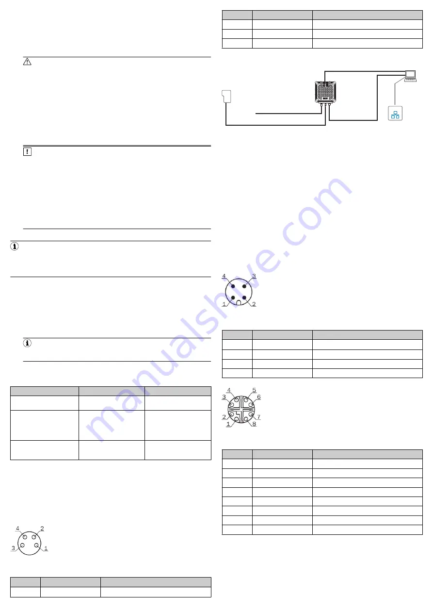
5.1 Connecting the device electrically
NOTE
The USB interface of the device is used in industrial environments only as a
service interface for temporary use (e.g. for configuration, troubleshooting).
Permanent use in real operation of the system as a host interface is not
intended.
Voltage supply
There are two ways to supply the device with voltage, as follows:
1.
Power and Ethernet: DC 18 V ... 30 V
°
Port 1: Power (24 V)
°
Port 2: Ethernet
2.
Power over Ethernet (PoE): DC 48 V / 57 V As per PoE technology
°
Port 1: Not assigned
°
Port 2: PoE
NOTE
The voltage supply via a power supply unit must be capable of bridging a
brief power failure of 20 ms.
It is possible to connect both variants at the same time; however, it is recom‐
mended to select just one variant.
Connecting connection variants at the same time
Initial situation
Adjustment
Effect
Voltage supply power via port
1
PoE via port 2 also con‐
nected.
No effect on the device sta‐
tus.
Voltage supply PoE via port 2
Power via port 1 also con‐
nected.
No effect on the device sta‐
tus.
Voltage supply with immedi‐
ate effect via power via port 1
(dominant).
Voltage supply power via port
1 (dominant) and PoE via port
2
Power via port 1 connection
is isolated.
Device restarts.
Voltage supply with immedi‐
ate effect via PoE via port 2.
After successful initialization, the
Ready
LED illuminates green.
Trigger
Read and write commands for the device can be started and ended using a trig‐
ger sensor. Trigger sensors can be connected directly to the device (port 3). The
permanently active supply voltage is received by the trigger sensor from the
device. Cover the male connectors with protective caps or male connectors when
port 3 is not in use. For additional information,
Port 3: Trigger
Figure 4: Female connector, 4-pin, A-coded
Pin assignment of the “Trigger” connection
Pin
Signal
Function
1
V
Trigger
Trigger supply voltage
Pin
Signal
Function
2
NC
NC
3
GND
Ground
4
Sensor 1
Digital input
5.1.1
RFU610-106xx: Power and Ethernet
Configuration
Diagnostics
Transponder
access
Reading result
SOPAS ET
SOPAS ET
PC
Ethernet
Ethernet
RFU610-106xx
"Ethernet" (Host/Aux1)
Cable
6
Cable
4
Cable
5
3
Trigger
sensor
1
"Power"
“USB“
7
(Aux 2)
2
Figure 5: Commissioning: Electrical connection block diagram of the
RFU610-106xx
1
Trigger sensor (read cycle)
2
Supply voltage V
S
3
Configuration, diagnosis, transponder access or display of read
results
4
Power adapter cable (female connector, M12, 4-pin, A-coded/open
ends)
5
Ethernet adapter cable (male connector, M12, 8-pin, X-coded/male
connector, RJ-45, 8-pin)
6
Trigger adapter cable (male connector, M8, 4-pin, A-coded/female
connector, M8, 4-pin, A-coded)
7
Adapter cable (male connector, 5-pin, USB, Micro-B type/male con‐
nector, 4-pin, USB, type A)
1.
Connect port 1 directly to a supply voltage via a power adapter cable (e.g.,
2095607).
2.
Connect port 2 directly to a PC via an Ethernet adapter cable (e.g.,
6049728).
3.
Connect the trigger sensor (e.g., GL6 (1059241)) directly to port 3 of the
device via a trigger adapter cable (e.g., 2096347).
Port 1: Power
Figure 6: Male connector, M12, 4-pin, A-coded
Pin assignment of the “Power” connection (M12)
Pin
Signal
Function
1
V
S
Supply voltage
2
NC
NC
3
GND
Ground
4
NC
NC
Port 2: Ethernet
Figure 7: Female connector, M12, 8-pin, X-coded
Pin assignment of the “Ethernet” connection
Pin
Signal
Function
1
TD+
2
TD-
Sender-
3
RD+
R
4
RD-
Receiver-
5
PoE-
Supply voltage-
6
PoE-
Supply voltage-
7
PoE+
Supply
8
PoE+
Supply
8023832//2019-04-15/en
RFU610 | SICK
3


