5.1.2
RFU610-106xx: Power over Ethernet (PoE)
RFU610-106xx (PoE connection)
Configuration
Diagnostics
Transponder
access
Reading result
4
SOPAS ET
SOPAS ET
PC
"Ethernet (AUX 1)"
Ethernet
Ethernet
Ethernet
Ethernet
PoE Switch
(Endspan)
...
DC 48 V/57 V
PSE
**)
PD
*)
*) PD = Powered Devices
2
**) PSE = Power Sourcing Equipment
3
"Ethernet"
Cable
5
"Ethernet (Host/Aux1)/Power"
Trigger
sensor
1
“USB“
7
(Aux 2)
RFU610-106xx
Cable
6
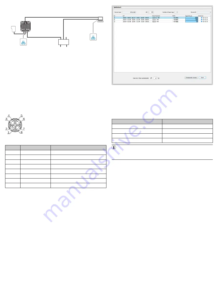
Figure 8: Commissioning: Electrical connection block diagram of the
RFU610-106xx
1
Trigger sensor (read cycle)
2
PD = Energy consumer
3
PSE = Energy source
4
Configuration, diagnosis, transponder access or display of read
results
5
PoE adapter cable (male connector, M12, 8-pin, X-coded/male con‐
nector, RJ-45, 8-pin)
6
Trigger adapter cable (male connector, M8, 4-pin, A-coded/female
connector, M8, 4-pin, A-coded)
7
Adapter cable (male connector, 5-pin, USB, Micro-B type/male con‐
nector, 4-pin, USB, type A)
1.
Connect port 2 directly to a PoE switch or PoE injector via a PoE adapter
cable (e.g., 6049728).
2.
Connect the trigger sensor (e.g., GL6 (1059241)) directly to port 3 of the
device via a trigger adapter cable (e.g.,2096347).
Port 2: PoE
Figure 9: Female connector, M12, 8-pin, X-coded
Pin assignment of the “PoE” connection
Pin
Signal
Function
1
TD+
2
TD-
Sender-
3
RD+
R
4
RD-
Receiver-
5
PoE-
Supply voltage-
6
PoE-
Supply voltage-
7
PoE+
Supply
8
PoE+
Supply
6
Commissioning and configuration with PC (Windows)
Adjustment of the device parameters to the application as well as diagnostics in
the event of malfunctions is undertaken by default with the SOPAS ET configura‐
tion software.
6.1 Installing and starting the configuration software
1.
Download and install the latest version of the SOPAS ET configuration soft‐
ware as well as the current device description files (
*.sdd
. In this case, select the “Complete” option as suggested by the
installation wizard. Administrator rights may be required on the PC to install
the software.
2.
Start the “SOPAS ET” program option after completing the installation. Path:
Start > Programs > SICK > SOPAS ET Engineering Tool > SOPAS.
3.
Establish communication between SOPAS ET and device with the automati‐
cally launching wizard. To do so, select the RFU610-106xx under the devices
available depending on the connected communication interface, e.g. in the
Ethernet (default Ethernet address: IP address: 192.168.0.1, subnet mask:
255.255.255.0). SOPAS ET establishes communication with the device and
loads the associated device description file. The
Quickstart
tab opens.
6.2 Detecting a transponder in Quickstart mode
1.
Bring one or more standards-compliant UHF transponders into the working
range of the internal antenna of the device. The UII/EPC of the individual
transponders must be differentiated so that several transponders can be
detected.
2.
Click the
Start
button on the
Quickstart
tab of SOPAS ET. SOPAS ET generates
an automated read cycle and lists the detected transponders one after
another in the Quickstart window.
Figure 10: SOPAS ET display of the detected transponders in the
Quickstart
win‐
dow
Feedback about transponder detection in the UHF field
In Quickstart mode, the default signals of the process feedback LEDs indicate
whether a UHF field is present and transponders have been detected. The
process feedback LEDs are located in the four corners of the antenna cover and
light up blue in this case. The option is available to choose between two bright‐
ness levels in SOPAS ET to adjust the brightness of the process feedback LEDs.
Process feedback LEDs
LED status
Status
Lit up (permanently)
0 transponders in field
Flashing slowly (f = 1.25 Hz)
1 transponder in field
Flashing quickly (f = 2.5 Hz)
2 transponders in field
Flashing faster (f = 5 Hz)
More than 2 transponders in field
NOTE
The automated triggering in Quickstart mode is intended for (initial) commis‐
sioning and not for permanent use when operating the device under real con‐
ditions.
6.3 Accessing the data on a transponder
1.
In order to access the memory area of a transponder, click the
Stop
button in
Quickstart
.
2.
Highlight the desired transponder (click it with the mouse).
3.
Click the
Transponder Access
button. The
Transponder Management Access
tab dis‐
plays the content of the selected transponder.
8023832//2019-04-15/en
RFU610 | SICK
4


