3.
Carefully insert the device into the cylinder.
4.
Mount and engage the contact carrier in the flange plate.
NOTE
When mounting the contact carrier in the flange, ensure the lug of the contact car‐
rier is aligned correctly.
5.
Press the flange plate into the bore in the cylinder wall.
6.
Fasten the flange plate using suitable screws or rivets.
7.
Use a specially prepared sleeve (e.g., made from polyamide) to locate the device in
its final position.
8.
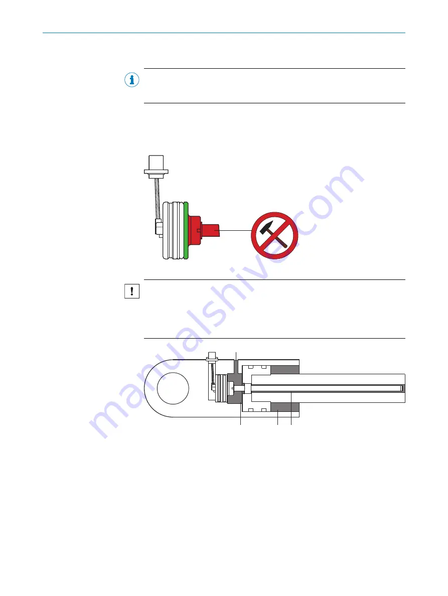
If necessary, carefully tap in the device and sleeve using a mallet.
Figure 15: Load-bearing surfaces
NOTICE
Risk of damage to the device during installation.
Forces acting on the load-bearing features of the housing can damage the device.
b
Do not apply any load on the pressure pipe or behind the head of the device
when mounting the sensor.
1
2
2
2
1
Oil inlet
2
Areas requiring lubrication
9.
Lubricate the indicated areas via the oil inlet.
Recommended screws for mounting the M12 flange
The screws should be selected so that no collision with the coupling nuts of the con‐
nected mating connectors can occur, e.g.,:
•
M3 socket head cap screw with flat head
•
DIN 912 hexagon socket head cap screw
•
ISO 14580 Torx screw
•
DIN 84 slotted-head screw
•
Comparable Phillips head screws or self-tapping screws
MOUNTING
4
8021473/2017-08-08 | SICK
T E C H N I C A L I N F O R M A T I O N | MAX48
17
Subject to change without notice


