Chapter 5 Equipment
T
-900 series
5-17
0093142132-00
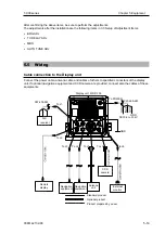
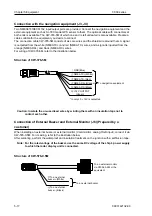
Connection with the navigation equipment (J3, J4)
Two NMEA0183/IEC61162 input/output ports are provided. Connect the navigation equipment and the
external equipment such as
SI-TEX
made GPS sensor to them. The optional cable with connectors at
both ends is available. The CW-376-5M of which one end is left untreated is also available. Prepare a
cable suitable for the equipment you desire to connect.
The connection cable CW-376-5M consists of six core wires and the shield wire around them. A signal
is outputted from the white (NMEA TX+) and red (NMEA TX-) wires, and a signal is inputted from the
orange (NMEA RX+) and black (NMEA RX-) wires.
For wiring of CW-376-5M, refer to the illustration below.
Structure of CW-376-5M
GND(Blue)
NMEA TX+(White)
To navigation equipment
NMEA TX-(Red)
NMEA RX+(Orange)
NMEA RX-(Black)
+12V OUTPUT
(Green)
* In only J3, +12V is outputted
Caution: Insulate the un-used lead wires by winding them with an insulation tape not to
contact each other.
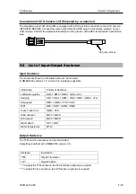
Connection of External Buzzer and External Monitor (J6) (Prepared by a
customer)
When installing an external buzzer or external monitor (VGA monitor, analog RGB input), connect it via
CW-576-0.5M. For its wiring, refer to the illustration below.
After soldering, perform the waterproof and insulation treatment on the junction with a self-fusion tape.
Note: For the rated voltage of the buzzer, use the same DC voltage of the ship’s power supply
to which the radar display unit is connected.
Structure of CW-576-0.5M
To an external buzzer
To an external monitor
via CW-560-2M or the
equivalent
To an external
(White)
To an external
buzzer- (Black)
Содержание MDC-921
Страница 2: ......
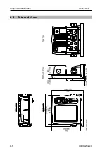
Страница 72: ...Chapter 6 Attached Table T 900 series 6 5 0093142132 00 6 3 External View...
Страница 80: ......
Страница 81: ......
Страница 82: ......
Страница 83: ......
Страница 84: ...11001 Roosevelt Blvd Suite 800 St Petersburg FL 33716 Tel 727 576 5995 Fax 727 576 5547 www si tex com...

