background image

T

-900 series Chapter 3 How to use the system menu 

0093142132-00 

3-5 

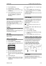
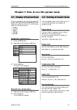
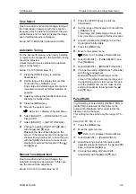
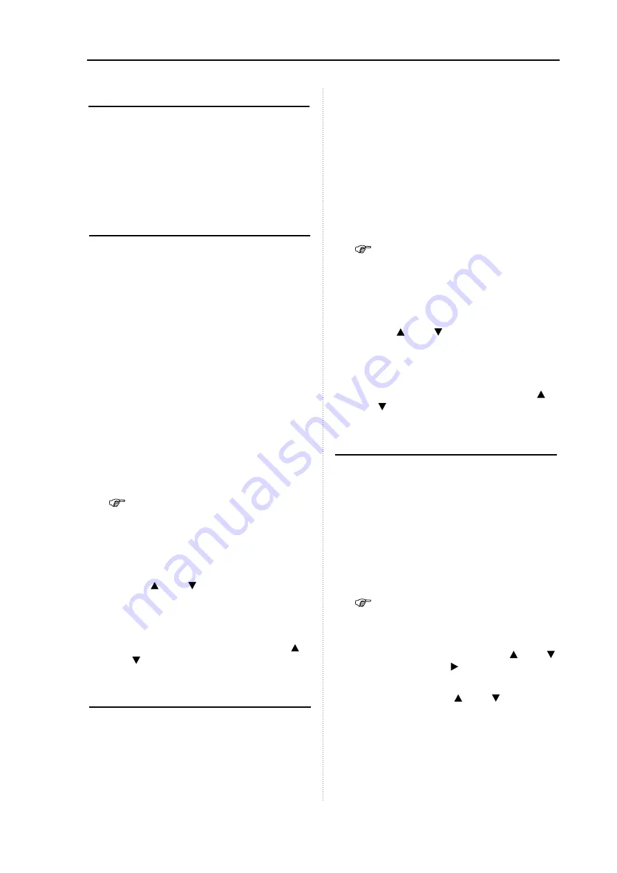
Tune Select 

Due to a sudden environment change, tuning of 
the transmission frequency with the reception 
frequency may be detuned. If detuned, the gain 
will decrease and it is hard to display the image 
even if setting remains unchanged.   

Setup: AUTO, MANUAL (Initial value: AUTO) 


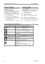
Automatic Tuning 

For the best performance, when newly installing 
or replacing the magnetron, the automatic tuning 
should be adjusted.   
Unless the auto tune is adjusted, the optimum 
gain is not achieved.   

Setup: 0 to 100 (Initial value: 31) 

Press the [STBY/TX] key to start the 
transmission. 

Set the range of the display to more than 
12nm with the [- RANGE +] key. 
Find a large and stable target of more 6nm 
(mountain or island) at farthest location as 
possible. 

Adjust by rotating the [GAIN] knob so that 
the target is faintly visible.   

Press the [MENU] key. 

Move to the system menu. 

  Refer to 3.1 Display of System Menu. 

Select [ADJUST] 

 [TUNE SELECT], and 

then [AUTO].   

Select [ADJUST] 

 [AUTO TUNE ADJ].   

Change the setting of [AUTO TUNE ADJ] 
with the [ ] and [ ] keys.   
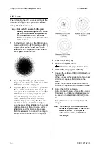
Maximize the size of fixed target on the 
screen. If the target becomes too large and 
the best tuning point is lost, reduce the gain 
with the [GAIN] knob once to make its size 
small and maximize the target with the [ ] 
and [ ] keys. 


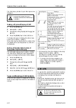
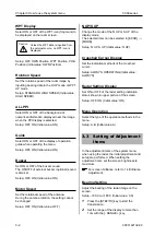
Manual Tune Adjustment 

Due to a sudden environment change, the 
automatic tuning may be detuned. In this case, 
use the manual tune adjustment.   

Setup: 0.0 to 100.0 (Initial value: 44.0) 


Press the [STBY/TX] key to start the 
transmission. 

Set the range of the display to 12nm with the 
[- RANGE +] key. 
Find a large and stable target of more than 
6nm (mountain or island) at farthest location   

Adjust by rotating the [GAIN] knob so that 
the target is faintly visible.   

Press the [MENU] key. 

Move to the system menu. 

  Refer to 3.1 Display of System Menu. 

Select [ADJUST] 

 [TUNE SELECT], and 

then [MANUAL].   

Select [ADJUST] 

 [MANUAL TUNE ADJ].   

Change the setting of [MANUAL TUNE ADJ] 
with the [ ] and [ ] keys.   
Maximize the size of fixed target on the 
screen. If the target becomes too large and 
the best tuning point is lost, reduce the gain 
with the [GAIN] knob once to make its size 
small and maximize the target with the [ ] 
and [ ] keys. 


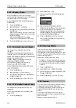
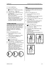
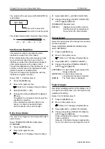
Pulse Width 

In [2.8 Setting of Pulse Width], [RESO-P PRI.] or 
[GAIN PRI.] is selected. At this moment, the 
pulse width (Displayed at the upper left of the 
display.) can be changed. 
This setting can be set for only the range (0.75 – 
8).  

Setup: SP, M1, M2, L1, L2 

Press the [MENU] key. 

Move the system menu. 

  Refer to 3.1 Display of System Menu. 

Select [ADJUST] 

 [PULSE WIDTH].   

Select the range in which the pulse width 
adjustment is performed with the [ ] and [ ] 
keys, and press the [ ] key. 

Change the setting of [Pulse Width 
Adjustment] with the [ ] and [ ] keys. 


Содержание MDC-921

Страница 1: ...product is specifically designed to be installed on boats and other means of maritime transport If your country forms part to the EU please contact your dealer for advice before attempting to install...

Страница 2: ......

Страница 3: ...apter unchanged The document No is indicated at the lower right side on the cover and at the left or right side of the footer region of each page Ban of Re use Transcription Unless the re use transcri...

Страница 4: ...trations may differ in physical font and shape And some parts may be omitted SI TEX is not liable or responsible for damage or trouble due to misunderstanding of the content described in this manual S...

Страница 5: ...s that the specific action is prohibited The inhibited action is displayed around the mark Cautions and Warnings on Equipment Be careful of rotating aerial The radar may start to rate without notice F...

Страница 6: ...and maintenance Be sure to turn off the power of the boat If the power switch is inadvertently turned on during work lethal electrocution could occur To prevent such an accident from occurring be sure...

Страница 7: ...hock or damage could occur The information displayed in this unit is not provided directly for your navigation For your navigation be sure to see the specified material Use the specified fuse If un sp...

Страница 8: ...to use F1 and F2 keys 1 8 1 10 Delete of Heading Line 1 9 Delete of Heading Line 1 9 1 11 Use of Crosshair Cursor 1 9 1 12 Measuring the distance and bearing between two points 1 10 Measuring the dist...

Страница 9: ...splay 2 13 Types and Meanings of ATA Symbols 2 13 Chapter 3 How to use the system menu 3 1 3 1 Display of System Menu 3 1 3 2 Setting of Assist Items 3 1 3 3 Setting of Adjustment Items 3 2 3 4 NMEA 3...

Страница 10: ...targets can be tracked The current motion of other ships can be grasped in a vector and numeral so that it helps your ship to navigate safely Optional By connecting the AIS receiver the gathered info...

Страница 11: ...C 1 to J4 Standard product Optional product Product prepared by a user ENT MENU RANGE GAIN TX BRILL 10 8 31 2VDC CCD camera External Monitor External Buzzer Display Unit MRD 103 Navigation Equipment N...

Страница 12: ...t Length Quantity 1 Display unit MRD 103 With mounting bracket and knobs 3 7kg 1 2 Hard cover E57MB11060 250g 1 3 DC power cable CW 265 2M 2m 1 4 Fuse F 1065 8A Cylinder 6 3x32 Normal fusion type for...

Страница 13: ...Heading measuring 2 AIS interface AIS 110 3 Cable for AIS receiver CW 376 5M With 6 pin waterproof connector and one end plain 5m 4 ATA interface MRE 340 5 Cables for external monitor external buzzer...

Страница 14: ...ction suppression effect The suppression effect becomes strong when rotating clockwise the knob and becomes weak when rotating counterclockwise the knob This function reduces the gain at a near distan...

Страница 15: ...ects near own ship can be easily confirmed 1 6 Switch over of range 4 Adjust the gain by rotating the GAIN knob Example of gain adjustment Too high gain Noise is also displayed Desired targets are dis...

Страница 16: ...1 1 How to read the radar screen FTC EBL VRM IN Off center Pulse width Range Fixed marker interval Display mode Heading Ship speed F2 key content F1 key content Enhance Alarm Trail Interference Reject...

Страница 17: ...0093142132 00 1 4 1 2 How to use the keys 1 2 3 4 5 6 7 8 9 10 ENT MENU RANGE GAIN STBY TX BRILL Various adjustment items can be set by operating each key The menu displayed by pressing the MENU key c...

Страница 18: ...m 5 MENU Opens or closes the menu 6 RANGE Changes the range setup 7 GAIN Rotate Changes the gain Push Changes the gain adjustment of sub screen lower screen of PPI PPI and the range 8 STC Rotate Chang...

Страница 19: ...guage 1 4 Brilliance Adjustment Brightness Adjustment of LCD The brilliance of menu can be adjusted to make it easier to see Setup 1 to 10 Initial value 10 1 Press the BRILL key briefly 2 Press the an...

Страница 20: ...snow to observe easily an image Gain Adjustment 1 When rotating clockwise the GAIN knob the gain increases When rotating counterclockwise the GAIN knob the gain decreases When the short distance or ta...

Страница 21: ...Land In the PPI PPI menu when rotating the STC knob the STC functions effective in both displays 1 9 Use of F1 and F2 keys The following functions can be assigned to the F1 and F2 keys FTC MODE DISPLA...

Страница 22: ...stored as a POB position In the state that the POB position is stored if the or key is pressed after pressing the F1 F2 key the setup of renewal release of the POB position can be changed The renewal...

Страница 23: ...mer How to connect a CCD camera 1 Connect the supplied cable CW 405 0 3M to the rear connector J7 2 Connect a commercially available CCD camera to the cable How to display the video of a CCD camera 1...

Страница 24: ...ected menu contents in the setup items at the right side change ECHO DISPLAY TRAILS ALARM OFF NEXT TRAIL MODE TRAIL TIME TRAIL SHAPE TRAIL LEVEL STANDARD 3MIN 7 ATA AIS 2 Press the key The displays of...

Страница 25: ...TM C UP RM C UP TM WPT UP RM Initial value H UP RM 1 Press the MENU key 2 Select ECHO MODE 3 Change the setting of MODE with the and keys 4 Press the MENU key to close the menu Four bearing displays o...

Страница 26: ...this mode is used in combination with the course up function of the plotter the understandable image is available 045 0 0 0 NORTH Land Target 1 Target 2 Own ship HDG WPT BRG Relative Motion RM and Tr...

Страница 27: ...ation based on your own ship s position Moving Fixed Own ship Moving Land True motion TM Your ship moves according to its speed and tidal current on the screen Stationary targets are fixed on the scre...

Страница 28: ...entire display Own ship Land PPI PPI Display Two radar images are displayed in the upper main screen and lower sub screen halves of the screen The screen is switched every two rotation of the antenna...

Страница 29: ...wn ship point is stored OFF CENTER OFF ON 4 Press the key 5 Move the crosshair cursor to the point you desire to move your ship with the keys 6 Press the ENT key Own ship s position moves to the posit...

Страница 30: ...AIL TIME with the and keys 6 Press the MENU to close the menu For the display method the relative display R and the true display T are provided When changing the range display mode or display select t...

Страница 31: ...of a target which is left as a trail is specified in TRAILS TRAIL LEVEL By increasing the numeral only trails of strongly reflected targets can be displayed By decreasing the numeral trails of weakly...

Страница 32: ...lines parallel with own ship are displayed Setup OFF ONE SIDE BOTH SIDES Initial value OFF 1 Press the MENU key 2 Select DISPLAY PI 3 Change the setting of PI with the and keys PI ONE SIDE BOTH SIDES...

Страница 33: ...ys and the bearing with the and keys 8 Press the ENT key Then the alarm range is set 9 Press the MENU key to close the menu The level of targets for alarm is set in ALARM DETECT LEVEL The alarm works...

Страница 34: ...ive Display Displays ships which are performing the information display or after performing it The dotted line denotes the speed and the real line denotes the heading The line perpendicular to the hea...

Страница 35: ...e ENT key 6 When acquiring several targets repeat steps 4 and 5 7 Press the MENU key to close the menu Target Level The signal level of a target to be automatic manual acquisition is specified in ATA...

Страница 36: ...1 Press the MENU key 2 Select ATA INFO 3 Change the setting with the and keys 4 Select ATA INFO NUMBER 5 Select the number with the and keys 6 Press the MENU key to close the menu Types and Meanings...

Страница 37: ...elect Prev with the and keys 2 Press the key The normal menu appears 3 2 Setting of Assist Items In the supplement items of the system menu to use the radar effectively the supplement functions are se...

Страница 38: ...onal speed of the antenna During the antenna rotation the setting cannot be changed Setup OFF ON Initial value OFF N UP S UP Change the mode of the N UP or S UP of the display mode The selected item c...

Страница 39: ...the RANGE key 3 Press the MENU key 4 Move to the system menu Refer to 3 1 Display of System Menu 5 Select ADJUST TX DELAY ADJ 6 Change the setting of TX DELAY ADJ with the and keys When the echo refle...

Страница 40: ...hown in Proper below when the sea surface reflected echo from near to far distance disappears evenly the STC curve set value is proper As shown in Large when the sea surface reflected echo at near dis...

Страница 41: ...l and maximize the target with the and keys Manual Tune Adjustment Due to a sudden environment change the automatic tuning may be detuned In this case use the manual tune adjustment Setup 0 0 to 100 0...

Страница 42: ...r of an image can be changed to make it easier to see Setup STANDARD DETAIL Initial value STANDARD 1 Press the MENU key 2 Move to the system menu Refer to 3 1 Display of System Menu 3 Select ADJUST EC...

Страница 43: ...ecuting KGC 1 SETTING 1 Press the MENU key 2 Move to the system menu Refer to 3 1 Display of System Menu 3 Select NMEA KGC 1 SETTING 4 Select Yes with the and keys 5 Press the ENT key Both the display...

Страница 44: ...program is displayed Antenna The state of the antenna is displayed The type of antenna connected and the state of voltage are displayed Panel Test Testing the operation block is performed LCD Test Tes...

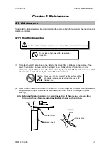
Страница 45: ...lightly and wipe the filter surface lightly with the cloth Do not use a dry cloth If done so due to static electricity the acrylic filter will attract dust Caution Never use a thinner solvent The filt...

Страница 46: ...turn off the power of the radar equipment to avoid the electrocution 1 Loosen the fixing screws and remove the cover of the antenna at the bow side The antenna drive motor can be seen at the lower sid...

Страница 47: ...isplayed Replacement target Normally 3 000 hours 4 4 Trouble Diagnosis In this chapter for finding a troubled location on a ship a simple troubleshooting is mentioned 4 4 1 Information required for re...

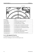
Страница 48: ...nna ANTENNA ERROR 2 The video signal is not inputted from the antenna ANTENNA ERROR 3 The heading signal is not inputted from the antenna ANTENNA ERROR 4 The auto tune is abnormal ANTENNA ERROR 5 The...

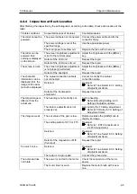
Страница 49: ...orrectly the mutual connection cable Detuned Re adjust Refer to Tune Select in 3 3 setting of Adjustment Items The character information can be displayed But the image of the radar cannot be displayed...

Страница 50: ...on from the sea surface becomes 3 Keep the surface of the platform where the antenna is installed horizontal as possible to be parallel with the sea surface 4 Install the antenna lock in front of the...

Страница 51: ...na Obstacle Keel line Distance to be shifted from the keel line Distance to an obstacle Diameter of an obstacle over the keel line How to shift the antenna from the keel line 2 How to keep an angle of...

Страница 52: ...ustration below make five 5 holes on the cradle and fix the bracket and the antenna together with hexagon bolts If the thickness of the bracket is 9 14mm it can be installed with the supplied bolts If...

Страница 53: ...of Open Antenna As illustrated below install the drive block facing the cut portion of the installation base toward the stern This makes it easier to perform the maintenance 1 Referring to the illustr...

Страница 54: ...0 04 0 16 in M10x45 pitch 1 5mm stainless 4 9 mm 0 16 0 35 in M10x50 pitch 1 5mm stainless 9 14mm 0 35 0 55 in M10x55 pitch 1 5mm stainless Included in accessories 14 19 mm 0 55 0 75in M10x60 pitch 1...

Страница 55: ...wer of the scanner unit is turned off Install the cable to the connector J5 at the rear of the display unit 2 Next remove the upper radome of the scanner unit lifting upward not to touch the aerial in...

Страница 56: ...ntenna 4kW 1 Confirm that the power of the scanner unit is turned off Install the antenna cable to the connector J5 at the rear of the display unit 2 Remove the upper radome of the scanner unit liftin...

Страница 57: ...er as shown in the illustration below 4 markings indicating the screw positions are marked on the upper and lower radomes respectively Install the radome aligning these markings Aerial Stern Radome bo...

Страница 58: ...n below Remove the heat contraction tube at the foot of the cable 7 Fix the cable with the holder plate At this moment fix the cable holder plate at one location Next tighten the shield wire of antenn...

Страница 59: ...onnection Diagram kW Radome Antenna RB714A 4kW Radome Antenna 4kWOpen Radome Antenna RB715A RB716A Antenna GND terminal Display Unit Violet Blue Yellow Shield Shield Shield Shield Violet Blue Yellow S...

Страница 60: ...isplay unit to the bracket 2 Remove the display unit from the bracket and place it on the stable flat place 3 Place the bracket on the position where the display unit will be installed and fix the bra...

Страница 61: ...n the desktop the maintenance space shown in the illustration below is required for cable lay out plugging in out of connector fuse replacement and bolt tightening Unit mm inch 100 3 15 16 3 15 16 9 2...

Страница 62: ...ont frame Refer to the illustration below 5 Connect all of the connectors for power antenna and others to the main unit 6 Insert the indictor in the place square hole and fix it with four pieces of 4m...

Страница 63: ...nit Connect the power cable antenna cable and cables of others to specified connectors of the display unit If optional navigation equipment and CCD camera are provided connect also the cables of these...

Страница 64: ...2132 00 Pin Assignment of Rear Connector The pin assignment is viewed from the rear of the display unit AIS Input Remote display NMEA IEC61162 Input Output NMEA IEC61162 Input Output External monitor...

Страница 65: ...1 Prepared by a customer Use the CW 376 5M Optional when installing the AIS receiver For connecting any equipment one end of the CW 376 5W is left un treated Prepare a connector suitable for the equip...

Страница 66: ...llustration below Structure of CW 376 5M GND Blue NMEA TX White To navigation equipment NMEA TX Red NMEA RX Orange NMEA RX Black 12V OUTPUT Green In only J3 12V is outputted Caution Insulate the un us...

Страница 67: ...shown on the table below can be received In NMEA0183 versions 1 5 2 0 and 3 0 inputting is possible Information Priority of Sentence Latitude Longitude GGA RMC RMA GNS GLL Heading HDT HDG HDM VHW RMC...

Страница 68: ...RAIL SHAPE STANDARD DECREMENT TRAIL LEVEL 1 7 7 EBL OFF ON VRM OFF ON COLOR STANDARD DAY NIGHT CURSOR SHAPE STANDARD LONG EBL VRM PI OFF ONE SIDE BOTH SIDES PI NUMBER 1 7 7 BRG TRUE REL REL TRUE VECTO...

Страница 69: ...ECT RANGE M OFF ON RANGE 2 16 SELECT RANGE L OFF ON RANGE 24 48 The maximum range differs depending on type of antenna ECHO COLOR BACK ECHO COLOR 1 7 TRAIL COLOR TRAIL COLOR 1 7 DISPLAY COLOR CURSOR C...

Страница 70: ...rm up time 2 min Antenna Pulse width 0 08 us 0 15 us 0 3 us 0 5 us 1 us Display unit MRD 103 Display 8 4 inch color TFT LCD Display VGA Effective diameter 127 4mm Display resolution 480 x 640 pixels O...

Страница 71: ...lay Unit CER 46 RB714A IPX6 RB715A RB716A Environment condition Vibration Resistant When the following vibration is applied to equipment respectively under specified condition its performance should n...

Страница 72: ...Chapter 6 Attached Table T 900 series 6 5 0093142132 00 6 3 External View...

Страница 73: ...00 6 6 Unit mm inch 100 3 15 16 3 15 16 9 29 64 240 100 Dimension drawing of table installation 240 9 29 64 8 21 32 220 224 Unit mm inch 8 5 32 Hole for installing 4 4mm screw R25 63 64 Threading hol...

Страница 74: ...er 6 Attached Table T 900 series 6 7 0093142132 00 RB714A Unit mm inch Weight 6kg RB715A Unit mm inch Weight 10kg 220 8 11 16 448 17 5 8 448 17 5 8 Bow Bow 636 25 1 16 255 10 1 16 636 25 1 16 660 25 6...

Страница 75: ...0 series Chapter 6 Attached Table 0093142132 00 6 8 RB716A Unit mm inch Weight 21kg RW701A 03 22kg RW701A 04 1034 RW701A 03 1346 RW701A 04 450 17 3 4 Bow 220 8 11 16 390 15 3 8 234 9 3 16 280 11 104 4...

Страница 76: ...ate Up to thousands of pulse waves are transmitted and received during one 360 degree rotation The typical radar antenna is a parabolic type or slotted array and its performance is essential for good...

Страница 77: ...n object such as sand a sandbar and muddy cay poor radar targets Since the distance from the coastline etc to your ship on a radar image to be seen as longer than that from the actual coastline more c...

Страница 78: ...mage 3 1 HU Real image False image Figure 7 5 False image by virtual image Duplicate target images When there is a big reflective surface nearby and perpendicular at a close distance i e when your shi...

Страница 79: ...nditions a duct occurs by the temperature inversion etc In this case the unusual propagation of the radio wave may reach distant targets out of radar range A target at more than the maximum range may...

Страница 80: ......

Страница 81: ......

Страница 82: ......

Страница 83: ......

Страница 84: ...11001 Roosevelt Blvd Suite 800 St Petersburg FL 33716 Tel 727 576 5995 Fax 727 576 5547 www si tex com...

Отзывы: