background image


Never let the power-cord come into contact with other cables! Handle the power-cord and all 
connections with the mains with particular caution! 


Never remove warning or informative labels from the unit. 


Never use anything to cover the ground contact. 


Never look directly into the light source. 


Never leave any cables lying around. 


Never use the device during thunderstorms, unplug the device immediately. 


Never leave various parts of the packaging (plastic bags, polystyrene foam, nails, etc.) within 
children‟s reach, as they are potential sources of danger. 


Do not insert objects into air vents. 


Do not open the device and do not modify the device. 


Do not connect this device to a dimmerpack. 


Do not shake the device. Avoid brute force when installing or operating the device. 


Do not switch the device on and off in short intervals, as this would reduce the system‟s life. 


Only use device indoor, avoid contact with water or other liquids. 


Only operate the device after having familiarized with its functions. 


Avoid flames and do not put close to flammable liquids or gases. 


Always allow free air space of at least 50 cm around the unit for ventilation. 


Always disconnect power from the mains, when device is not used or before cleaning! Only 
handle the power-cord by the plug. Never pull out the plug by tugging the power-cord. 


Make sure that the device is not exposed to extreme heat, moisture or dust. 


Make sure that the available voltage is not higher than stated on the rear panel. 


Make sure that the power-cord is never crimped or damaged. Check the device and the power-
cord from time to time. 


Make sure that no side forces can impact on the truss system. 


The cable insert or the female part in the device must never be strained. There must always be 
sufficient cable to the device. Otherwise, the cable may be damaged which may lead to deadly 
electrical shocks. 


If the external cable is damaged, it has to be replaced by a qualified technician. 


If the lens is obviously damaged, it has to be replaced. So that its functions are not impaired, due 
to cracks or deep scratches. 


If device is dropped or struck, disconnect mains power supply immediately. Have a qualified 
engineer inspect for safety before operating. 


If the device has been exposed to drastic temperature fluctuation (e.g. after transportation), do 
not switch it on immediately. The arising condensation water might damage your device. Leave 
the device switched off until it has reached room temperature. 


If your Showtec device fails to work properly, discontinue use immediately. Pack the unit securely 
(preferably in the original packing material), and return it to your Showtec dealer for service. 


For adult use only. The device must be installed out of the reach of children. Never leave the unit 
running unattended. 


For replacement use fuses of same type and rating only. 


The user is responsible for correct positioning and operating of the Spectral D4000. The 
manufacturer will not accept liability for damages caused by the misuse or incorrect installation 
of this device. 


This device falls under protection class I. Therefore it is essential to connect the yellow/green 
conductor to earth. 


Repairs, servicing and electric connection must be carried out by a qualified technician. 


WARRANTY: Till one year after date of purchase. 


CAUTION ! EYEDAMAGES !. 

Avoid looking directly into the light source. 

(meant especially for epileptics) !


Содержание Spectral D4000

Страница 1: ...Spectral D4000 IP67 ORDERCODE 43504 ...

Страница 2: ... on Showtec for more excellent lighting products We design and manufacture professional light equipment for the entertainment industry New products are being launched regularly We work hard to keep you our customer satisfied For more information iwant showtec info You can get some of the best quality best priced products on the market from Showtec So next time turn to Showtec for more great lighti...

Страница 3: ...g without ID addressing DMX Addressing with ID Address MENU OVERVIEW Creating a static color Activating an Auto Program Run Mode DMX 512 Address Personality ID Address Edit Custom Changing the Settings White Settings White Balance Activating the Password How to make your own Custom Program Modes 11 channel STAG 3 channel ARC 1 RGB 4 channel AR1 d Master Dimmer RGB 4 channel ARC 2 RGBW 5 channel AR...

Страница 4: ...o 50 000 hours will be achieved under normal operational conditions If improving on this lifespan expectancy is of a higher priority place care in providing for lower operational temperatures This may include climatic environmental and the reduction of overall projection intensity SAFETY INSTRUCTIONS Every person involved with the installation operation and maintenance of this device has to be qua...

Страница 5: ...ime Make sure that no side forces can impact on the truss system The cable insert or the female part in the device must never be strained There must always be sufficient cable to the device Otherwise the cable may be damaged which may lead to deadly electrical shocks If the external cable is damaged it has to be replaced by a qualified technician If the lens is obviously damaged it has to be repla...

Страница 6: ...r safety issues Do not attempt the installation yourself Always let the installation be carried out by an authorized dealer Procedure If the Spectral D4000 is lowered from the ceiling or high joists professional trussing systems have to be used Use a clamp to mount the Spectral D4000 with the mounting bracket to the trussing system The Spectral D4000 must never be fixed swinging freely in the room...

Страница 7: ...double boxing is always a safe method to use Note If you are given an RMA number please include the following information on a piece of paper inside the box 1 Your name 2 Your address 3 Your phone number 4 A brief description of the symptoms Claims The client has the obligation to check the delivered goods immediately upon delivery for any short comings and or visible defects or perform this check...

Страница 8: ...e barndoors to direct output optional LED display with lock out feature 15 optics Beam angle 11 Field angle 23 Lux 15 060 91 2 m Light source 48 LEDs 12 x 750 mA red 12 x 1 000 mA green 12 x 1 000mA blue 12 x 1 000 mA white Power and current 230 V 50 Hz 178 9 W 0 78 A operating 0 81 A inrush Double bracket yoke doubles as floor stand NOTE Knowledge of DMX is required to fully utilize this unit DMX...

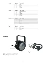
Страница 9: ...ription 1 Master Dimmer 2 Red 3 Green 4 Blue 5 White Ar2 s Channel Description 1 Master Dimmer 2 Red 3 Green 4 Blue 5 White 6 Strobe HSV Channel Description 1 Hue 2 Saturation 3 Value Overview 1 2 Fig 1 1 18 x 1 Watt 6x Red 6x Green 6x Blue 2 Mountingbracket for Truss mounting ...

Страница 10: ... DMX signal connector OUT 4 5 6 7 Note You cannot plug a standard DMX cable directly into the connector Be sure to use the included special cable for DMX connection Female 3 pin DMX to special 3 pin Male Male 3 pin DMX to special 3 pin Female Powercable to special 3 pin Female ...

Страница 11: ...serial data link must be daisy chained in one single line To comply with the EIA 485 standard no more than 30 devices should be connected on one data link Connecting more than 30 fixtures on one serial data link without the use of a DMX optically isolated splitter may result in deterioration of the digital DMX signal Maximum recommended DMX data link distance 100 meters Maximum recommended number ...

Страница 12: ...SSING 1 Connect a DMX controller example 50720 Showdesigner 1024 to the series of Spectral D4000 s 2 Each Spectral D4000 has 11 DMX channels DMX address LED Par 1 1 Par 2 12 Par 3 23 Par 4 34 etc 3 The ID address has not been set so therefore when using the controller CH11 must be inactive CH11 0 It is also possible to deactivate the ID address by selecting ID OFF from the Settings menu 4 Any DMX ...

Страница 13: ...esigner 1024 50720 Example 1 The figure above shows a simple DMX layout All the Spectral D4000 s have different ID addresses which allows the user to collectively control the whole group of Spectral D4000 s with the same DMX address by setting CH11 to 0 or to control each Spectral D4000 independently by first selecting the DMX address and then by using CH11 to locate the target ID address S howdes...

Страница 14: ...12 MENU OVERVIEW ...

Страница 15: ...DOWN buttons to change the static colors Red Green Blue White or the strobe speed 0 20Hz Press MENU to go 1 step back You can combine RED GREEN BLUE and WHITE to create an infinite range of colors 0 255 Red White Set the value of the red LEDs 0 255 Set the value of the white LEDs 0 255 Green Strobe Set the value of the green LEDs 0 255 Set the value of the flash 0 20Hz Blue Set the value of the bl...

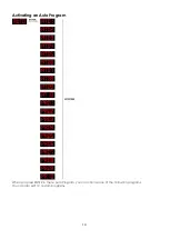
Страница 16: ...14 Activating an Auto Program When you press ENTER in menu Auto Program you can choose one of the 10 built in programs You can also edit 10 custom programs ...

Страница 17: ...ration the RUN MODE does not work DMX 512 Address When you press ENTER in menu DMX 512 address you can set the DMX address You can choose your DMX address between 0 512 Personality Enter the PERSONALITY mode to select a DMX mode STAG ARC1 AR1d ARC2 AR2d AR2s HSV STAG 11 channels ARC1 3 channels AR1d 4 channels ARC2 4 channels AR2d 5 channels AR2s 6 channels HSV 3 channels ID Address Enter the ID A...

Страница 18: ...r the EDIT CUSTOM mode to edit the custom programs PR01 PR10 Each custom program has 30 steps which can be edited Each step allows the creation of a scene using RED GREEN BLUE WHITE STROBE TIMER FADE Changing the Settings ...

Страница 19: ...n set This means RGB 255 255 255 The color is displayed as you have calibrated the specific color in menu CAL2 RGBW When it is set to NO on RGB 255 255 255 the RGB values are not adjusted and the output is most powerful The RGB s parameter can be adjusted in CAL2 5 Enter POW menu to choose NORM or HIGH power operation mode When the Spectral D4000 is in normal mode the power consumption is about 90...

Страница 20: ...hite color will be made by the actual RGB values on the CAL2 Menu Activate Password Enter the KEY LOCK mode to select whether the access password is On or Off The Access Password UP DOWN UP DOWN When you have pressed ENTER in menu KEY ON it will take 30 seconds before the LED Par is locked When the password is activated the display will ask for password each time the fixture is powered on ...

Страница 21: ...ues Use Up Down to change the values Use Up Down to change the values Use Up Down to change the values Use Up Down to change the values Use Up Down to change the values Use Up Down to change the values And so you can add a maximum of 30 scenes After that you can start with PR02 and create a maximum of 30 scenes again You can repeat these steps until you ve reached PR10 step 30 This means it is pos...

Страница 22: ...Red Down Green 100 Blue 0 Red 0 Green 100 Blue Up Red 0 Green Down Blue 100 Red Up Green 0 Blue 100 Red 100 Green 0 Blue Down Red 100 Green Up Blue Up Red Down Green Down Blue 100 Red 100 Green 100 Blue 100 White 100 White 1 3200K White 2 3400K White 3 4200K White 4 4900K White 5 5600K White 6 5900K White 7 6500K White 8 7200K White 9 8000K White 10 8500K White 11 10000K 7 000 010 Strobe No Functi...

Страница 23: ...currently projected color When the fader is at 255 the intensity of the output is at its maximum RED GREEN BLUE WHITE SELECTION Channels 2 3 4 and 5 control the overall intensity of each respective color Channels 2 3 4 and 5 can be combined to create an unlimited range of colors COLOR MACROS WHITE BALANCE Channel 6 selects the required COLOR MACRO and whites in different colors Channel 6 has prior...

Страница 24: ...ontrol ARC2 Channel Value Function 1 000 255 Red 0 100 2 000 255 Green 0 100 3 000 255 Blue 0 100 4 000 255 White 0 100 DMX Control AR2 d Channel Value Function 1 000 255 Dimmer 0 100 2 000 255 Red 0 100 3 000 255 Green 0 100 4 000 255 Blue 0 100 5 000 255 White 0 100 DMX Control AR2 s Channel Value Function 1 000 255 Dimmer 0 100 2 000 255 Red 0 100 3 000 255 Green 0 100 4 000 255 Blue 0 100 5 00...

Страница 25: ...ddress 11 234 ID address 45 120 129 ID address 12 235 ID address 46 130 139 ID address 13 236 ID address 47 140 149 ID address 14 237 ID address 48 150 159 ID address 15 238 ID address 49 160 169 ID address 16 239 ID address 50 170 179 ID address 17 240 ID address 51 180 189 ID address 18 241 ID address 52 190 199 ID address 19 242 ID address 53 200 209 ID address 20 243 ID address 54 210 ID addre...

Страница 26: ...24 Beam Angles ...

Страница 27: ...ectric power The operator has to make sure that safety relating and machine technical installations are to be inspected by an expert after every year in the course of an acceptance test The operator has to make sure that safety relating and machine technical installations are to be inspected by a skilled person once a year The following points have to be considered during the inspection 1 All scre...

Страница 28: ... 15 060 91 2 m Power and current 230 V 50 Hz 178 9 W 0 78 A operating 0 81 A inrush Double bracket yoke doubles as floor stand Operating modes 11 channel STAG Master Dimmer RGBW Color Macro Strobe Auto Custom Programs Auto Speed Adjustment Dimmer Speed ID Address Selection 3 channel ARC 1 RGB 4 channel AR1 d Master Dimmer RGB 4 channel ARC 2 RGBW 5 channel AR2 d Master Dimmer RGBW 6 channel AR2 s ...

Страница 29: ......

Отзывы: