


For now, leave the machine unplugged from the wall and take some time
to review the controls. You will notice that the DRO display was mounted
upside down during shipping in order to clear the bench legs. At this point
you can remove the nut from the mounting stud and turn the display right
side up. The functions and features of the DRO are covered in the DRO
manual itself. The mill head was placed at its lowest level for shipping, so
you can now unfold the handle from the wheel and move the mill head
upwards manually. There is no lock on the travel, as the stepper motors
lock it into place when at rest. You can also move the Y axis forward and
back and the X axis left and right, but be sure to loosen the carriage locks.
On the front panel to the left are all the controls for the spindles and CNC.
Your machine PC has been pre-configured as well as the VFD inverter, so
your machine will be fully functional when you get ready to turn it on.
Toward the top of the front left panel is the VFD keypad and display. In the
delivered setup, all the functions of the VFD are controlled through Mach 3,
and the display will simply read the Hz reading going to your motors. Please
note, this is not the RPM of the spindle, that will read on your Mach 3
screen. This key pad can also be configured for manual control with the
small knob and the buttons. There is a decal telling how to change the codes
between manual and Mach 3 control. This is all covered in the V-8 manual.
Below the VFD Key pad are the machine controls. The top left switch is for
selecting which spindle will run. Later on you will note that when selecting
either lathe or mill, you will hear a snap sound from the inside of the panel-
that is the magnetic contactor engaging. To the right of this switch is your
main power switch for the VFD inverter and the spindle motors. When this
switch is on, you will also have the red light on. Below these switches in the
center is the E-Stop switch. This switch shuts off all power to the VFD
inverter as well as the stepper motors, so in the event of a crash, all you need
to do is push the red button in. To re-engage the switch you just turn it
clockwise, but be sure to read the instruction and turn off all other switches
first. Below the E-Stop and to the left is the power switch for the Gecko
drive. When this switch is on, your CNC system is activated. To its right is
the stepper motor switch. With the CNC on and the stepper switch on, the
stepper motors are locked in position and can only be moved by Mach 3. If
you want to move the carriages manually, you must turn the stepper switch
off. Check each switch and watch to be sure it is properly “clocked” so the
white stripe points to the proper place on the decal. On the panel at 90
degrees to the switches you will find the flow regulator for the air coolant
system. You will note the air exits through a flex nozzle on a magnetic base
which can be used as a coolant for the cutting tools. Opposite the controls on
the rear of the panel you will find the inlet for the coolant air.
Above the air inlet is the Gecko drive to which the computer and stepper
motors are attached. You will see that Z and X axes are not hooked up, and
A and Y axes are open for use with other CNC tools like the CNC toolpost.
You will also see a small slide switch marked CHARGE PUMP. This should
remain in the ON position. The charge pump is a safety feature that prevents
Содержание MILL TURN
Страница 12: ......
Страница 13: ......
Страница 14: ......
Страница 15: ...5C COLLET SET 4 JAW CHUCK ...
Страница 16: ...FOLLOW REST ...
Страница 17: ...STEADY REST ...
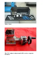
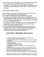
Страница 18: ...TOOL TRAY The CNC toolpost setup manual will be sent as a separate document ...