


17
Mounting the Antenna Bay(s)
4
Mounting the Antenna Bay(s)
Mount the antenna
bays.
WARNING
Whenever a rigger is on the tower in the area of the antenna, shut off
the signal and lock it off so that it cannot be turned on accidentally. RF
emissions at close range are hazardous.
CAUTION
Do not attach the bays together with the RF cable before mounting
them. NEVER try to support the bays from the cable.
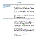
a. Using the galvanized 5/8" hardware (
), attach the
threaded rods (
NOTE
Mount antenna bays with feed straps up, clear of all guylines and other
obstructions.
b. Using the galvanized 5/8" hardware, attach the clamp halves (
) to the
threaded rods (
), encircling the mounting pole as shown. Do not tighten
the hardware fully yet.
c. Repeat for the other antenna bay(s) as applicable.
d. Ensure the bays are located on the mounting pole at the locations you
marked.
e. Align the bays to the correct azimuth and vertically with each other, then
tighten the mounting hardware to 37 ft-lb.
NOTE
The Model 6842 does not require pressurization or purging. The feed
system up to the bays may be pressurized.
Please proceed to
Connecting the Antenna (single-bay)
Connecting the Antenna (2-bay)
on page 31 as applicable.
Figure 12. Bay mounting on pole
Содержание 6842
Страница 4: ......
Страница 8: ......
Страница 11: ...3 Preparation Figure 1 Tower layout single bay antenna ...
Страница 12: ...Preparation 4 Figure 2 Tower layout two bay antenna ...
Страница 13: ...5 Preparation Figure 3 Tower layout three bay antenna ...
Страница 14: ...Preparation 6 Figure 4 Tower layout four bay antenna ...
Страница 15: ...7 Preparation Figure 5 Tower layout five bay antenna ...
Страница 16: ...Preparation 8 Figure 6 Tower layout six bay antenna ...
Страница 17: ...9 Preparation Figure 7 Tower layout eight bay antenna ...
Страница 18: ...Preparation 10 Figure 8 Top mounted installation ...
Страница 22: ......
Страница 26: ......
Страница 32: ......
Страница 37: ...29 Connecting the Antenna 2 bay Figure 17 Two way power divider mounted and connected ...
Страница 38: ......
Страница 46: ...Startup 38 Figure 21 Apply the signal ...
Страница 48: ......
Страница 51: ...43 Parts Figure 23 Endseal radome components ...
Страница 58: ......
Страница 59: ...51 Appendix A Selected Assembly Drawings The following are excerpts from selected assembly drawings ...
Страница 60: ...52 Figure A 1 22 Feed Strap with Endseal Radome Deicer ...
Страница 61: ...53 Figure A 2 6842 Exploded View with Endseal Radome ...
Страница 62: ...54 Figure A 3 Bay Arm Stickers ...
Страница 63: ...55 Figure A 4 Power Divider Mount Detail ...
Страница 64: ......


