


25
Connecting the Antenna (single-bay)
6
Connecting the Antenna (single-bay)
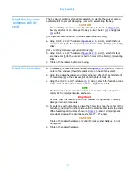
Connect the antenna
bay.
a. Provide a gas stop between the tower transmission line and the antenna
input if necessary. The antenna bay is not pressurized. The feed system up
to the bay may be pressurized.
CAUTION
All O-rings are made of silicone. Do not lubricate them with silicone
grease, as this will soften the O-ring. Use only a light lubricating coat of
O-Lube (provided) or petroleum jelly; too much may hamper electrical
contact and contaminate the interior of the system.
Be sure the O-ring is properly seated in its groove and not pinched
between the flange contact surfaces.
b. Coat the flange O-ring (
) lightly with O-Lube, then install it in
the O-ring groove in the flange.
c. Before connecting the cable to the radiator, make sure an inner conductor
connector is in place in the inner conductor of the input flange.
Figure 15. Single bay antenna
connection
Содержание 6842
Страница 4: ......
Страница 8: ......
Страница 11: ...3 Preparation Figure 1 Tower layout single bay antenna ...
Страница 12: ...Preparation 4 Figure 2 Tower layout two bay antenna ...
Страница 13: ...5 Preparation Figure 3 Tower layout three bay antenna ...
Страница 14: ...Preparation 6 Figure 4 Tower layout four bay antenna ...
Страница 15: ...7 Preparation Figure 5 Tower layout five bay antenna ...
Страница 16: ...Preparation 8 Figure 6 Tower layout six bay antenna ...
Страница 17: ...9 Preparation Figure 7 Tower layout eight bay antenna ...
Страница 18: ...Preparation 10 Figure 8 Top mounted installation ...
Страница 22: ......
Страница 26: ......
Страница 32: ......
Страница 37: ...29 Connecting the Antenna 2 bay Figure 17 Two way power divider mounted and connected ...
Страница 38: ......
Страница 46: ...Startup 38 Figure 21 Apply the signal ...
Страница 48: ......
Страница 51: ...43 Parts Figure 23 Endseal radome components ...
Страница 58: ......
Страница 59: ...51 Appendix A Selected Assembly Drawings The following are excerpts from selected assembly drawings ...
Страница 60: ...52 Figure A 1 22 Feed Strap with Endseal Radome Deicer ...
Страница 61: ...53 Figure A 2 6842 Exploded View with Endseal Radome ...
Страница 62: ...54 Figure A 3 Bay Arm Stickers ...
Страница 63: ...55 Figure A 4 Power Divider Mount Detail ...
Страница 64: ......