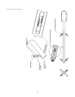
Parts
46
Table 11. Components, feed system for 5-bay antenna
Part Number
Description
5-bay
Qty.
NOTE
Feed system for 3- to 8-bay arrays is shown in
34. 98141-G504
Mount, 3-1/8" power divider
2
35. 01/2-13SS
•
Nut, hex 1/2-13 SS
5
36. G12SSF
•
Washer, flat 1/2" SS
6
37. G12R-8
•
Rod, threaded, 1/2-13 x 8" galvanized
2
38. 98141-03
•
Channel, power divider
1
39. 01/2SSS
•
Washer, lock, 1/2" galvanized
5
40. DCP
•
Clamp half, 5.75" bolt spacing
1
41. G1205
•
Bolt, hex head 1/2-13 x 5" galvanized
1
42. 98359-05
•
Spacer, universal mount, transformer &
transmission line
1
43. 98359-G503
•
Saddle assembly, power divider mount
2
44. 6114-400
Clamp, hose
4
49. 318F-078F x 5
Power divider, 5-way, 3-1/8" EIA to 7/8" EIA
1
26. 9068-215
O-ring for 7/8" EIA flange
10
27. 82912-G507M
Kit, hardware for 7/8" EIA flange
10
31. 99715-G5xx
Coax cable section, HCA78-50J, 7/8" EIA to
7/8" EIA
5
28. TY529MX
Tie-wrap
a/r
46. 9068-340
O-ring for 3-1/8" EIA flange
1
47. 82912-G503
Kit, hardware for 3-1/8" EIA flange
1
Table 12. Components, feed system for 6-bay antenna
Part Number
Description
6-bay
Qty.
NOTE
Feed system for 3- to 8-bay arrays is shown in
34. 98141-G504
Mount, 3-1/8" power divider
2
35. 01/2-13SS
•
Nut, hex 1/2-13 SS
5
36. G12SSF
•
Washer, flat 1/2" SS
6
37. G12R-8
•
Rod, threaded, 1/2-13 x 8" galvanized
2
38. 98141-03
•
Channel, power divider
1
39. 01/2SSS
•
Washer, lock, 1/2" galvanized
5
40. DCP
•
Clamp half, 5.75" bolt spacing
1
41. G1205
•
Bolt, hex head 1/2-13 x 5" galvanized
1
42. 98359-05
•
Spacer, universal mount, transformer &
transmission line
1
43. 98359-G503
•
Saddle assembly, power divider mount
2
Содержание 6842
Страница 4: ......
Страница 8: ......
Страница 11: ...3 Preparation Figure 1 Tower layout single bay antenna ...
Страница 12: ...Preparation 4 Figure 2 Tower layout two bay antenna ...
Страница 13: ...5 Preparation Figure 3 Tower layout three bay antenna ...
Страница 14: ...Preparation 6 Figure 4 Tower layout four bay antenna ...
Страница 15: ...7 Preparation Figure 5 Tower layout five bay antenna ...
Страница 16: ...Preparation 8 Figure 6 Tower layout six bay antenna ...
Страница 17: ...9 Preparation Figure 7 Tower layout eight bay antenna ...
Страница 18: ...Preparation 10 Figure 8 Top mounted installation ...
Страница 22: ......
Страница 26: ......
Страница 32: ......
Страница 37: ...29 Connecting the Antenna 2 bay Figure 17 Two way power divider mounted and connected ...
Страница 38: ......
Страница 46: ...Startup 38 Figure 21 Apply the signal ...
Страница 48: ......
Страница 51: ...43 Parts Figure 23 Endseal radome components ...
Страница 58: ......
Страница 59: ...51 Appendix A Selected Assembly Drawings The following are excerpts from selected assembly drawings ...
Страница 60: ...52 Figure A 1 22 Feed Strap with Endseal Radome Deicer ...
Страница 61: ...53 Figure A 2 6842 Exploded View with Endseal Radome ...
Страница 62: ...54 Figure A 3 Bay Arm Stickers ...
Страница 63: ...55 Figure A 4 Power Divider Mount Detail ...
Страница 64: ......


