FreeScan UE_ User Manual _V1.2.0.0 20
Adjust View
⚫
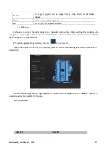
Hold down the left button and move the mouse to rotate the model.
⚫
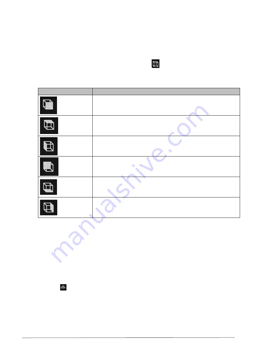
Alternatively, select the perspective selecting button, click
located at the bottom of the interface,
and select different previews under various perspectives.
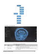
Introduction to perspective adjustment
Icon
Description
Front view, viewing the object to be scanned from the front perspective.
Top view, viewing the object to be scanned from the top perspective.
Left view, viewing the object to be scanned from the left side perspective.
Rear view, viewing the object to be scanned from the rear perspective.
Bottom view, viewing the object to be scanned from the bottom perspective.
Right view, viewing the object to be scanned from the right side perspective.
Create a Cutting Plane
Taking a cutting plane as reference, scanning above this plane is deemed as valid. Users can choose whether
the scanned data below the cutting plane shall be saved. If the user chooses not to save the scanned data
below the said plane, the invalid data will be deleted instantly. On the other hand, if the user chooses to save
the scanned data below the said plane, the invalid data obtained through scanning will not be deleted and
when a new scanning is conducted, no new data will be appended pertaining to the area below the reference
cutting plane.
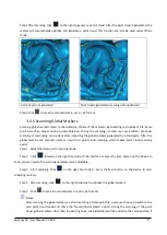
Step 1 Click
and the cutting plane window pops out.
Step 2 Choose how to create the cutting plane.
⚫
Point cloud fitting: the plane formed by the selected point cloud data is deemed as the cutting
plane.


