


D. Press the bearing and shaft assembly into the housing (18). In applicable pump models, replace the internal snap ring (17). On
newer model pumps, the bearings will be flush to the end of the housing or slightly protruding, and will be retained with the
flange adapter (24). The adapter (24) may be reassembled to the pump housing (18) at this time with the two or four bolts (21)
as applicable. The use of Loctite #262 or equivalent is recommended on the adapter bolts. Torque the adapter bolts to 18 ft-lbs.
E. The seal seat (14) is now installed from the impeller end of the housing. The grey silicon carbide or white ceramic seat should
be placed against the grey silicon carbide or black carbon seal face of the mechanical seal (15). Care must be taken to remove
all burrs from the keyway to prevent cutting of the rubber cup. If possible, a half thickness key can be used to assist in
assembly. In pressing the ceramic and boot, a pusher should be used with a diameter only slightly greater than the shaft
diameter (.80"). Soapy water or a lubricant from a seal manufacturer may be used in assembly. Oil or grease must not be used
as it will prevent the rubber cup from properly gripping the shaft. The seat and cup are pressed just beyond the external/snap
ring groove. The seat should be inspected to insure that the cup did not become partially dislodged during the press procedure.
The washer (11) and external snap ring (10) are then installed.
F.
The internal wear plate (13) is dropped in place, anti-rotation pin aligned with the cast slot in the bottom of the housing. The
cam (8) is reinstalled and secured with the cam screw (9). Older model cam screws were sealed by means of a nylon washer
requiring Permatex or other sealant to seal the cam screw. The cam screw should be inspected to insure that it does not
protrude below the cam. This condition is possible if the nylon seal is badly deformed or if a substitute screw is used. Should
the screw protrude beneath the cam, replace it with a new screw, or grind flush. Failure to do so will result in immediate
impeller damage.
G. At this time, if applicable, press on any gears (25), pulleys, or hubs onto the shaft. While pressing on the drive mechanism, the
shaft (19) must be securely supported from the impeller end and in line with the press. Failure to do so will result in either
damaged bearings and/or a canted gear with excessive run out. For the base model pumps P1716, P1722, P1727, P1730 and
P1731, replace the tapered gear and gear nut on the shaft. Use Loctite #262 on the gear threads and torque the nut to 50 ft-
lbs. For all other tapered gear and shaft assemblies, see the applicable engine manufacturers’ requirements for thread sealant
and torque specifications.
H. Install the impeller (7) using a non-petroleum based lubricant such as silicon or soapy water.
Note
: Do not use petroleum-
based fluids as they will damage the impeller. The impeller is installed using a twisting motion. Ensure the impeller blades are
bent in the same direction as upon removal. Once installed, rotate the shaft to align keyway and slide the key (6) in place. Then
cover the key hole in the impeller insert with the rubber end plug (5).
Caution:
Failure to place the plug in place on the 17000A
impeller will cause the key to walk out of the shaft keyway and damage the cover. The 17000 impeller requires that the key be
placed on the shaft prior to installation.
I.
Replace the cover o-ring (4), cover (3), with the cover cap screws (1). Torque the cap screws to 14 ft-lbs.
Note
: If the cover is
replaced with a new one, record the information on the original cover to help identify the pump for future repairs and mainte-
nance.
J.
After installation, inspect the pump seal, lip seal, body, housing and cam areas for leaks.
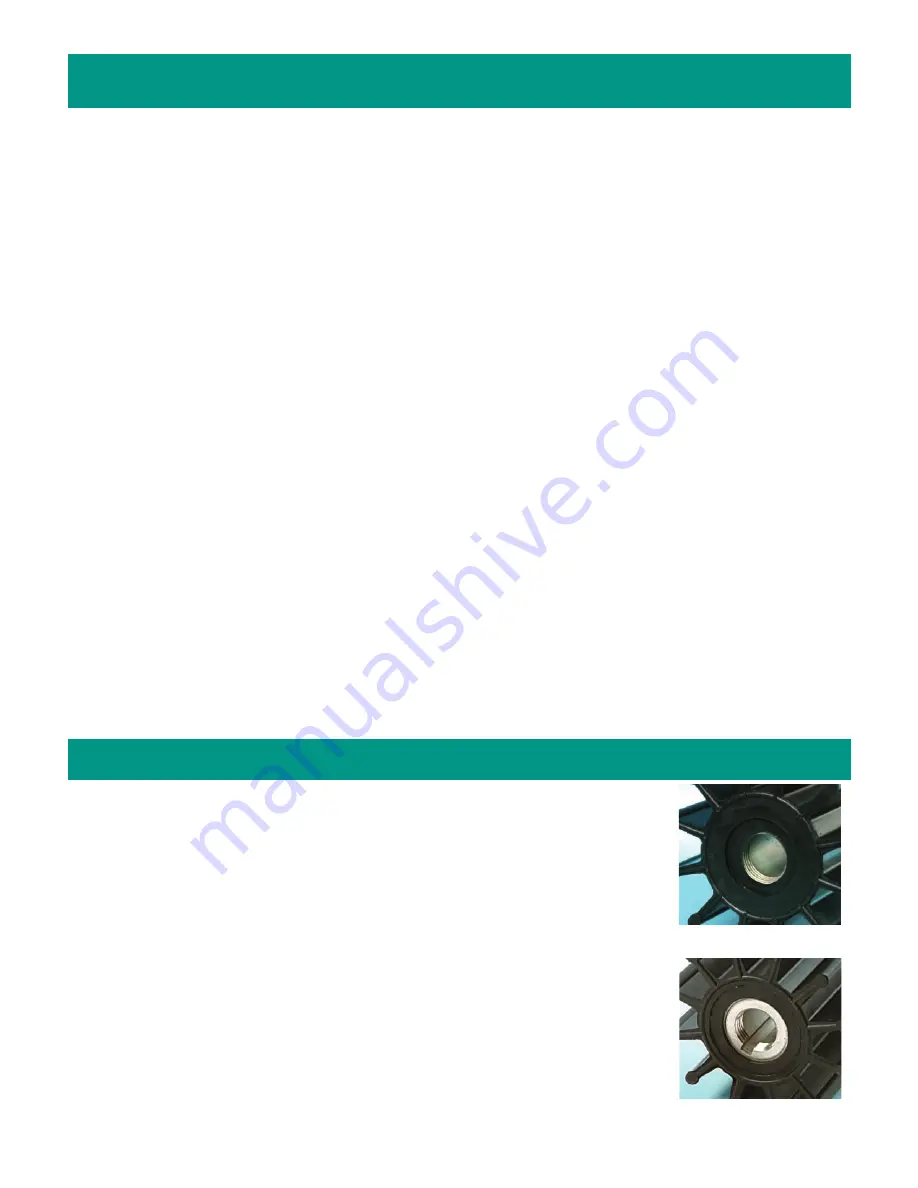
17000A —
Impeller with
threaded/thru-key insert
allows for ease of installation in hard-to-reach
applications as well as easy removal. As the impeller puller is threaded in the impeller insert and
jacks against the pump shaft, the patented threaded insert allows for easy removal. The thru-key
aspect of the impeller allows for the impeller to be installed prior to placing the key in the shaft key-
way, therefore, making the installation process easier. (Patent No. 6,116,855)
17000K —
Impeller Kit
• Kit Contains: 17000A Impeller with
threaded/thru-key insert
, o-ring and rubber cap.
17000 —
Impeller only, which uses a
threaded insert
for ease of removal (Patent No. 6,116,855).
27000K —
Impeller Kit (Patent No. 6,116,855)
• Kit Contains: 27000 splined impeller and o-ring.
Assembly / Disassembly Instructions (continued)
17000 Impeller Options
Threaded Impellers
(17000 and 27000)
Threaded Thru-Key
Design Impellers
(17000A)
3


