background image

33

Poor AM Reception

 

Often one of the main complaints about poor AM 

reception is that the same AM station can be heard at 

different frequencies. Check to see that BOTH wires of 

the AM loop antenna are connected. A loop antenna is 

required for AM reception, as it forms part of the front-

end tuned circuit.

Poor FM Reception

 

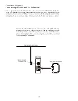
The antenna may be incorrectly attached.

 

Station not correctly tuned in, weak or off the air.

 

You can improve reception by using external antennas. 

Some cable TV feeds also offer FM reception.

Input Selection Problems

 

If you find that certain inputs cannot be selected, Check 

the INPUTS menu of the OSD.

There is No TV Picture

 

Make sure that the video input of your TV monitor is 

connected to the Main monitor output on the SR-120 

rear panel.

 

Check that the correct video input is selected on your 

Monitor, and is configured correctly.

 

Check the video connection from your selected source 

component to the SR-120.

 

Make sure that you are using the correct video 

connections. If in doubt, try connecting the video output 

from your source directly to your TV monitor. This will 

help you narrow down the problem.

No Equalization or Decoding Options Don’t Work

 

Check what mode you have selected; remember that, 

in Direct modes, and when using the 7.1 channel direct 

inputs, equalization and surround decoding options are 

not active.

No Dolby Digital or DTS Playback

 

Look for the Dolby Digital or DTS Logo on the source 

program’s box or sleeve. Make sure your player’s digital 

output is set to BITSTREAM for Dolby Digital or DTS. 

This is often a player’s setup menu item, not the disc’s 

menu. Some discs are available with a number of different 

options, such as Dolby Digital or Dolby Pro Logic. 

Make sure that you have selected the correct mode from 

your player’s menu. Only digital inputs will work for 

these modes. Check that your player’s digital output is 

connected to the appropriate corresponding digital input 

on your SR-120.

 

There is no AC-3 RF input connection for Laserdisc 

players. You will need an external RF demodulator.

 

Check the calibration procedure from time to time. This 

is an excellent way of checking that all speakers are 

working correctly.

 

Noise bursts are heard when DTS encoded CDs or LDs 

are played. Compressed DTS data uses the normal digital 

audio tracks of CDs and LDs. This analog noise may be 

heard in your system before the DTS digital signal is 

locked on. 

No On-Screen Display

 

Press the remote’s MENU button to activate the OSD. It 

should be present even when no video source has been 

selected. Remember, there is no OSD “Pop Up” for 

component video connections.

Sound drops out with CD or DVD playback

 

Make sure the disc is not dirty or scratched.

 

Some inexpensive players and changers tend to mistrack 

more often, causing dropouts.

Remote Not Working

 

Make sure the batteries are not dead, or installed 

incorrectly.

 

Make sure that the SR-120 front panel receiver window 

is not obstructed.

 

Check that the front or rear IR receivers have not been 

turned off in the OSD CONTROL menu.

Zone 2 Not Working

 

Zone 2 is set “disabled” from the factory, so you must 

use the OSD Zone 2 menu (or the remote control) to turn 

it On.  

 

If it is the Zone 2 SPEAKERS that are not working, verify 

that the rear panel INTERNAL AMPLIFIER DEFEAT 

switch is set to Off (green LED is On) and the ZONE 2 

switch is set to Z2.

Main Speakers Not Working

 

Verify that the rear panel INTERNAL AMPLIFIER 

DEFEAT switch is set to Off (green LED is On).

 

Verify that the front panel channel status LEDs are all 

lit blue (if one is lit red, this indicates a fault with that 

amplifier or associated speaker and wiring).

Zone 2 Does Not Play Digital Inputs

 

Zone 2 can play analog sources independent of what is 

playing in the Main Zone. It cannot play from a digital-

only source unless that input is selected and playing in 

the Main Zone. To play a source such as a DVD player 

in Zone 2 independent of the Main Zone, make sure you 

connect the player’s L/R analog audio output to the SR-

120 too.

Содержание SR-120

Страница 1: ...1...

Страница 2: ...ng a DVD Video Player Using Digital Audio Component Video 24 Connecting a DVD Video Player Using Analog Audio Composite Video 25 Connecting to a TV or Projector Using Digital Audio Component Video 26...

Страница 3: ...Cirrus 32 bit dual core DSPs for unequaled high resolution HD audio decoding and signal management Genesis ST Torino high performance scaling engine featuring a full implementation of the Faroujda DCD...

Страница 4: ...he SR 120 directly above other heat producing equipment unless sufficient ventilation or forced air cooling is provided Do not install the SR 120 in locations without proper ventilation The SR 120 sho...

Страница 5: ...lift out the unit and remove all the packing material and accessories It is important to save all the packing materials and the box in case your Sherbourn SR 120 ever needs to be moved or shipped bac...

Страница 6: ...ion of the Faroudja DCDi image processing suite Intuitive full color graphical OSD with adjustable trans parency presented over live video including HDMI Unique automatic multi channel room correction...

Страница 7: ...ovided a SEPARATE electrical connection on a SEPARATE circuit This configuration yields the most stable power supply in any home theater application regardless of your equipment choices Refer to your...

Страница 8: ...ble HDMI supports standard enhanced or high definition video plus multi channel digital audio on a single cable It transmits all ATSC HDTV standards and supports 8 channel 192kHz uncompressed digital...

Страница 9: ...e remote control and the VFD and LEDs all remain off check to make sure the power cord is plugged in and the ON OFF rocker switch on the back of the SR 120 is in the ON position Note The Standby LED A...

Страница 10: ...emote control to work 8 MUTE Button This turns off the sound Press it again or adjust the volume control to return to the previous volume level 9 DIM Button The front panel display has ten levels of i...

Страница 11: ...nnect to the inputs of your external amplifiers and powered sub woofer s There are outputs for Front Left Front Right Left Surround Right Surround Center Channel Subwoofer Left Back Surround and Right...

Страница 12: ...will be seen on the TV screen 14 Component Video In Component Video In These inputs connect to the component video outputs of your DVD SAT or other video source if they have this capability Note that...

Страница 13: ...er Switch This switch controls the electrical power to the entire unit When this switch is Off the SR 120 is totally off When this switch is On the SR 120 is controlled by the front panel power button...

Страница 14: ...and the minus ends are aligned within the markings in the battery compartment in the remote control Loading the batteries into the remote To ensure that you get the most usable time from your remote...

Страница 15: ...on the front panel produces the same result 2 OFF This turns the unit off and returns it to standby mode Note Please turn the volume down on the SR 120 before turning it off When it is turned on the S...

Страница 16: ...ND OR ZONE 2 speaker outputs the amplifiers must also be enabled POWER This button switches the power to Zone 2 On and Off If Zone 2 is on and you turn off the SR 120 the Standby LED will remain blue...

Страница 17: ...display completely Off 16 RETURN This button returns you to the previous screen and if pressed repeatedly will exit menu 17 MENU This button displays the OSD menu 18 NAVIGATION ARROWS These buttons a...

Страница 18: ...elections will offer additional choices on sub menus to the right This menu selects the current viewing mode Preferred modes can also be configured for each individual input and type of source PARAMET...

Страница 19: ...r each source the range is from 0mS to 200mS in 1mS increments Trigger This is where you select which triggers are activated when this input is selected to turn on other equipment when this particular...

Страница 20: ...right and left speakers be set to large Speaker Setup This is where you configure your SPEAKER SIZE CROSSOVER LEVEL CALIBRATION SPEAKER DISTANCE SPEAKER LEVEL LFE LEVEL and HDMI AUDIO OUTPUT Speaker...

Страница 21: ...to be extremely quiet during this initial phase Turn off all fans air conditioners and other equipment that will disturb the room s ambient sound levels The next screen will read Test ambient result T...

Страница 22: ...allow you to take advantage of all the latest High Definition and Lossless audio and video formats and is the preferred method of connection when available When you select DVD on the SR 120 the audio...

Страница 23: ...the Red Blue Green trio Note Digital audio connections are necessary to decode surround sound encoded material such as Dolby Digital or DTS Use Coaxial shown or Optical cables When you select DVD on...

Страница 24: ...re than Composite Video but not as good as component or HDMI When you select DVD on the SR 120 the audio output from the DVD player will play through the audio system and video will appear on the TV o...

Страница 25: ...V or Projector There may be more than one input on high end video screens In this example HDMI would have been a better choice This will give the best analog picture quality especially if the video so...

Страница 26: ...present The 7 1 channels of audio completely bypass all digital processing functions of the SR 120 including tone controls surround processing and bass management features This provides the purest si...

Страница 27: ...from the CD player will play through the audio system While this method of connection is preferred if the CD player is not equipped with a digital output either optical or coaxial as shown you may cho...

Страница 28: ...the Cassette Tape Deck for recording you also must connect the SR 120 s TAPE audio outputs into the Cassette Tape Deck inputs may also be labeled RECORD Note The Tape Deck outputs are sometimes labele...

Страница 29: ...tyle connector and have a 75 Ohm impedance A 300 ohm antenna may be used as in the example if it is matched to the 75 ohm input by using a balun Position the AM and FM antennas where reception is best...

Страница 30: ...oser than this you can experiment by adding sound deadening material such as drapes on the walls to reduce any unwanted reflections The Center Speaker Most movie dialog will come from the center speak...

Страница 31: ...arrival time of the sound emanating from the subwoofer to coincide with the bass from your main speakers If your subwoofer is located far from your main speakers adjusting this control may enable you...

Страница 32: ...during normal use of your unit If problems persist contact Sherbourn Technical Support The SR 120 will not turn on No Power Important Please note the SR 120 requires initialization after the power cor...

Страница 33: ...propriate corresponding digital input on your SR 120 There is no AC 3 RF input connection for Laserdisc players You will need an external RF demodulator Check the calibration procedure from time to ti...

Страница 34: ...sts disconnect all the source components one at a time from the back of the SR 120 until you identify the problem Ground loop isolators are available for audio lines and video Ask your Sherbourn Deale...

Страница 35: ...r has been removed defaced or replaced in any way Damage to or loss of any software or data residing on the product if applicable is not covered When providing repair or replacement service Sherbourn...

Страница 36: ...ity listening experience at any volume level More than 40 years of engineering experience in noise reduction perceptual audio coding and related psychoacoustic technologies have resulted in the develo...

Страница 37: ...37 Sherbourn Technologies Inc 131 SE Parkway Court Franklin Tennessee 37064 Tel 615 791 4046 Fax 615 791 6287 Web www sherbourn com...

Отзывы: