background image

Connections and Setup

-17

Connecting to
Component Video
Equipment Using a
Component Cable
(INPUT 1)

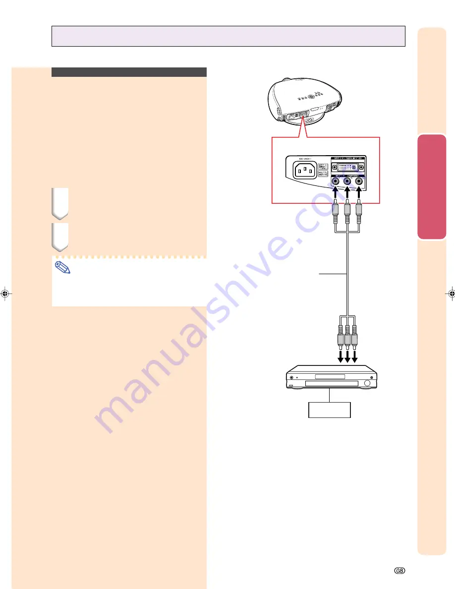
Use a component cable when connecting com-
ponent video equipment such as DVD players
and DTV decoders to INPUT 1 terminals.

1

Connect a component cable to
the projector.

2

Connect the above cable to the
component video equipment.

Note

Make sure to turn both the projector and
the video equipment off before connect-
ing.

Connecting to a DVD Player and DTV Decoder

To analog component
output terminal

To INPUT 1 terminals

DVD player or
DTV decoder

Component cable

(commercially available)

XV_Z201E_E_p13_24.p65

03.10.30, 12:17AM

17

Содержание XV-Z201E

Страница 1: ...AIS 1 70 SVENSKA 1 70 ESPAÑOL 1 70 ITALIANO 1 70 NEDERLANDS 1 70 CTOR KTOR CTEUR KTOR CTOR TORE CTOR XV Z201E OPERATION MANUAL BEDIENUNGSANLEITUNG MODE D EMPLOI BRUKSANVISNING MANUAL DE MANEJO MANUALE DI ISTRUZIONI GEBRUIKSAANWIJZING ...

Страница 2: ...coloured blue must be connected to the terminal which is marked with the letter N or coloured black The wire which is coloured brown must be connected to the terminal which is marked with the letter L or coloured red IF YOU HAVE ANY DOUBT CONSULT A QUALIFIED ELECTRICIAN This equipment complies with the requirements of Directive 89 336 EEC and 73 23 EEC as amended by 93 68 EEC Dieses Gerät entspric...

Страница 3: ...tain this information Before recycling the packaging please be sure that you have checked the contents of the carton thoroughly against the list of Supplied accessories on page 12 Model No XV Z201E Serial No WARNING The cooling fan in this projector continues to run for about 90 seconds after the projector enters the standby mode During normal operation when putting the projector into the standby ...

Страница 4: ...AL HAZARD OF GLASS PARTICLES IF LAMP HAS RUPTURED HANDLE WITH CARE SEE OPERATION MANUAL DU REMPLACEMENT DE LA LAMPE PRECAUTIONS A OBSERVER LORS DEBRANCHER LE CORDON D ALIMENTATION AVANT DE RETIRER LES VIS L INTERIEUR DU BOITIER ETANT EXTREMEMENT CHAUD ATTENDRE 1 HEURE AVANT DE PROCEDER AU REMPLACEMENT DE LA LAMPE NE REMPLACER QUE PAR UNE LAMPE SHARP DE TYPEBQC XVZ200 1 RAYONSULTRAVIOLETS PEUVENT E...

Страница 5: ... Settings 40 Menu Bar Items 42 Adjusting the Picture 44 Adjusting Image Preferences 44 Adjusting the Colour Temperature 45 Gamma Correction Function 46 Emphasizing the Contrast 46 Picture Setting Function 47 Adjusting the Computer and DVD DTV Images 48 When Auto Sync is OFF 48 Special Modes Adjustment 49 Auto Sync Adjustment 50 Checking the Input Signal 50 Using the Options Menu 51 Checking the La...

Страница 6: ...Do not overload wall outlets and extension cords with too many products because this can result in fire or electric shock 15 Never push objects of any kind into the Projector through the cabinet slots as they may touch high voltage points or cause a short circuit This could result in a fire or electric shock 16 Do not attempt to service the Projector yourself Opening or removing covers may expose ...

Страница 7: ...ing type power outlet Digital Light Processing DLP Digital Micromirror Device and DMD are trademarks of Texas Instruments Microsoft and Windows are registered trademarks of Microsoft Corporation in the United States and or other countries PC AT is a registered trademark of International Business Machines Corporation in the United States Macintosh is a registered trademark of Apple Computer Inc in ...

Страница 8: ...emely hot during projector operation To pre vent injury do not touch these areas until they have sufficiently cooled down Allow at least 30 cm of space between the exhaust ventilative hole and the nearest wall or obstruction If the cooling fan becomes obstructed a protection device will automatically turn off the projector lamp This does not indicate a malfunction Remove the projector power cord f...

Страница 9: ...audio cable 4 Plug the power cord into the AC socket of the projector and into the wall outlet Page 14 5 Remove the lens cap from the lens 7 Press on the remote control to select the INPUT 4 mode Page 31 On screen Display 8 Turn on the video equipment To INPUT 4 terminal To video out put terminal INPUT 4 button ON button ON Video equipment Video cable 9 Play the video 10 Adjust the image size imag...

Страница 10: ...trol sensor Lens cap Zoom knob 25 Exhaust ventilative hole 6 Focus ring 25 25 Lens shift dial 39 ENTER button 33 KEYSTONE button ON button 30 STANDBY button 32 47 PICTURE SETTING button Attaching the Lens Cap The lens cap can be attached to the projector using commercially available straps for cellular phones etc as shown in the figure Projector Side and Rear View Numbers in refer to the main page...

Страница 11: ...4 VIDEO terminal RCA 20 DIGITAL INPUT TYPE switch 15 INPUT 3 S VIDEO terminal 4 pin Mini DIN 23 RS 232C terminal 9 pin D sub 11 Remote control sensor 14 Attaching the Terminal Cover 1 Align with the tabs on the projector and then press the terminal cover in the direction of the arrow 2 Tighten the two screws on the bottom of the projector Removing the Terminal Cover 1 Loosen the two screws on the ...

Страница 12: ...1 31 31 35 47 35 STANDBY button ENTER button 33 KEYSTONE button UNDO button INPUT 1 button INPUT 2 button INPUT 4 button AUTO SYNC button RESIZE button PICTURE SETTING button MENU button 30 ON button ADJUSTMENT buttons ƒ ß INPUT 3 button DIGITAL INPUT button RGB COMP button Remote control signal transmitters ...

Страница 13: ...es Do not mix new and old batteries This may shorten the life of new batteries or may cause old batteries to leak Remove the batteries from the remote control once they have run out as leaving them can cause them to leak Battery fluid from leaked batteries is harmful to your skin therefore be sure to first wipe them and then remove them using a cloth The batteries included with this projector may ...

Страница 14: ...epending on the region projectors are shipped with only one power cord see above Use the power cord that cor responds to the wall outlet in your country 3 RCA to 15 pin D sub cable 3 0 m AN C3CP DVI to 15 pin D sub adaptor 20 cm AN A1DV DVI cable 3 0 m AN C3DV Note Some of the cables may not be available depending on the region Please check with your nearest Sharp Authorised Projector Dealer or Se...

Страница 15: ...Connections and Setup Connections and Setup ...

Страница 16: ...e Be sure to read the operation manuals of the devices to be connected before making connections This projector can be connected to Video equipment A VCR DVD player or other video equipment See page 15 A DVD player or DTV decoder See page 17 DTV is the umbrella term used to describe the new digital television system in the United States A computer using DVI to 15 Pin D sub adapter See page 21 A DV...

Страница 17: ...eo cable to the video equipment Note The INPUT 3 S VIDEO terminal uses a video signal system in which the picture is separated into color and luminance sig nals to realize a higher quality image To view a higher quality image use a com mercially available S video cable to con nect the INPUT 3 terminal on the projec tor and the S video output terminal on the video equipment S video cable commercial...

Страница 18: ...r other video equipment can be con nected to INPUT 4 input terminal 1 Connect a composite video cable to the projector 2 Connect the composite video cable to the video equipment To INPUT 4 terminal VCR or other video equipment To video output terminal Composite video cable 16 Connecting the Projector to Other Devices ...

Страница 19: ...V decoders to INPUT 1 terminals 1 Connect a component cable to the projector 2 Connect the above cable to the component video equipment Note Make sure to turn both the projector and the video equipment off before connect ing Connecting to a DVD Player and DTV Decoder To analog component output terminal To INPUT 1 terminals DVD player or DTV decoder Component cable commercially available ...

Страница 20: ...humbscrews 3 Connect the above cable to the video equipment Note When connecting this projector to com ponent output terminal of the DTV de coder select Component for Signal Type on the OSD menu or press on the remote control See page 52 Make sure to turn both the projector and the video equipment off before connect ing 3 RCA to 15 pin D sub cable Type AN C3CP 3 0 m DVI to 15 pin D sub adaptor Typ...

Страница 21: ... INPUT 2 terminal 1 Connect a DVI to 15 pin D sub adaptor to the projector 2 Connect the above adaptor to an RGB cable 3 Connect the above cable to the video equipment Secure the connectors by tightening the thumbscrews Note When connecting this projector to DVI out put of the DTV decoder select RGB for Signal Type on the OSD menu or press on the remote control See page 52 To RGB output terminal R...

Страница 22: ...the DIGITAL INPUT terminal 3 Connect the other end to the corresponding terminal on the DVD player or DTV decoder Secure the connectors by tightening the thumbscrews Note Select DIGITAL INPUT mode when con necting to video equipment with the digi tal output terminal See page 31 Make sure to turn both the projector and the video equipment off before switching the DIGITAL INPUT TYPE switch and conne...

Страница 23: ...als other than those listed may cause some of the functions not to work When connecting the projector to a computer in this way select RGB for Signal Type on the OSD menu or press on the remote control See page 52 A Macintosh adaptor may be required for use with some Macintosh computers Contact your nearest Sharp Authorised Projector Dealer or Service Centre Depending on the computer you are using...

Страница 24: ...he projector and then the computer Be sure that the computer is the last de vice to be turned on after all the connec tions are made Plug and Play function This projector is compatible with VESA standard DDC 1 DDC 2B The projector and a VESA DDC compatible computer will communicate their setting requirements allowing for quick and easy setup Before using the Plug and Play function be sure to turn ...

Страница 25: ...uter Note Do not connect or disconnect an RS 232C cable to or from the computer while it is on This may damage your computer The RS 232C function may not operate if your computer terminal is not correctly set up Refer to the operation manual of the computer for details Refer to Computer Compatibility Chart on page 66 for a list of computer signals compatible with the projector Use with computer si...

Страница 26: ...ng the Swivel Stand You can adjust the angle and direction of the projected image by using the Swivel Stand 1 Unlock the lever on the Swivel Stand 2 Adjust the angle and direction of the projected image as you want by lifting up the projec tor and rotating the projector on the Swivel Stand 3 Lock the lever on the Swivel Stand Removing the Swivel Stand 1 Lift the projector 2 with pressing the remov...

Страница 27: ...ivel Stand Focusing and Zooming The picture can be focused and zoomed in or out by using the Focus ring and the Zoom knob 1 Rotate the Focus ring until the image on the screen comes into focus 2 Slide the Zoom knob The im age can be adjusted to the de sired size within the zoom range Using the Lens Shift The picture can be adjusted within the shift range of the lens by rotating the lens shift dial...

Страница 28: ...m projection distance Minimum projection distance Diag Horizontal Placement range c Projection distance a Composite S video 480I P 1080I 720P RGB Vertical placement range e Projection distance b Composite S video 480I P 1080I 720P RGB Vertical placement range f Horizontal Placement range d a 0 029330688x 0 038639669 x Screen size diag in b 0 02434978x 0 034646716 6 4m 20 10 4 8m 15 7 4 2m 13 10 3 ...

Страница 29: ...perpendicular to the screen with all feet flat and level Tilting or angling the projector will reduce the effectiveness of the lens shift function Screen size 254 cm Aspect ratio 16 9 Screen Upper and Lower Lens Shift Position Ceiling Mount When the projector is in the inverted position use the upper edge of the screen as the base line and exchange the lower and upper lens shift values Screen Lowe...

Страница 30: ...al Sharp ceiling mount bracket for this installation Before mounting the projector remove the Swivel Stand See pages 24 and 25 for removing and attaching the Swivel Stand Before mounting the projector contact your nearest Sharp Authorised Projector Dealer or Service Centre to obtain the recommended ceiling mount bracket sold separately AN TK202 ceiling mount bracket AN TK201 extension tube AN 60KT...

Страница 31: ...Basic Operation Basic Operation ...

Страница 32: ...linking green LAMP indicator shows that the lamp is warming up Wait until the indicator stops blinking before operating the projector If the power is turned off and then im mediately turned on again it may take a short while before the lamp turns on Note After the projector is unpacked and turned on for the first time a slight odour may be emitted from the ex haust ventilative holes This odor will...

Страница 33: ... im ages from equipment connected to INPUT 3 terminal Used for projecting im ages from equipment connected to INPUT 4 terminal Used for projecting images from equipment connected to DIGITAL INPUT terminal INPUT 1 Compo nent INPUT 2 Compo nent RGB INPUT 3 S Video INPUT 4 Video DIGITAL On screen Display Selecting the On screen Display Lan guage English is the preset language for the On screen Displa...

Страница 34: ... do not want to put the projector into the standby mode wait until the confirmation message disappears 2 Unplug the power cord from the AC outlet after the cooling fan stops Info Do not unplug the power cord dur ing projection or cooling fan opera tion This can cause damage due to the rise in internal temperature as the cooling fan also stops When connected to equipment such as an amplifier be sur...

Страница 35: ...ged when adjusting the Key stone setting When adjusting H Keystone and V Keystone at the same time the values of adjustable angles for each setting become smaller The adjustable value of the V Key stone becomes extremely small when H Keystone is made to be the maximum value Keystone correction is disabled while the picture mode is set to SMART STRETCH See page 35 4 To return to the normal screen p...

Страница 36: ...n See page 24 3 Align the edge of the screen closest to the projector with the test pattern by adjusting the zoom and the Swivel Stand See pages 24 and 25 4 Adjust the Keystone function so that the size of the projected image matches the screen size See page 33 5 Align the image on the screen by adjusting the zoom function and the Swivel Stand 6 Adjust the focus so that the projected image is in f...

Страница 37: ... from the cur rently connected device Adjusting the Picture Aspect Ratio This function allows you to modify or custom ize the picture display mode to enhance the input image Depending on the input signal you can choose SIDE BAR SMART STRETCH CINEMA ZOOM or STRETCH image Press Each time is pressed the picture mode changes as shown on the next page FREEZE button RESIZE button RESIZE button ...

Страница 38: ...t ratio Squeeze 4 3 aspect ratio Note SMART STRETCH cannot be selected while the Keystone correction page 33 is being adjusted Keystone correction page 33 is disabled while the picture mode is set to SMART STRETCH 580I 580P is displayed on the screen when signal 576I 576P is input Image Projection 768 576 1024 576 480I 480P 576I 576P NTSC PAL SECAM VGA SVGA XGA 768 576 1024 576 480P 720P 1024 576 ...

Страница 39: ...Adjustments and Settings Adjustments and Settings ...

Страница 40: ...stment and setting For adjusting the menu items see pages 38 and 39 For setting the menu items see pages 40 and 41 Menu screen example ENTER button UNDO button MENU button buttons ENTER button UNDO button MENU button buttons Menu Selections Adjustments 1 Press The menu screen is displayed Note The Picture menu screen for the selected input mode is displayed ...

Страница 41: ... for INPUT 3 or 4 For items on the menus see the tree charts on pages 42 and 43 3 Press or to select the item you want to adjust Note To display a single adjustment item press after selecting the item Only the menu bar and the selected adjustment item will be displayed Then if you press or the fol lowing item Bright after Con trast will be displayed Press to return to the previous screen 4 Press o...

Страница 42: ...y the other menu screens The menu icon for the selected menu screen is highlighted Note The Fine Sync menu is not avail able for INPUT 3 or 4 For items on the menus see the tree charts on pages 42 and 43 Menu icon Menu screen Picture Fine Sync Options Language PRJ Mode ENTER button UNDO button MENU button buttons ENTER button UNDO button MENU button buttons Select the menu icon ...

Страница 43: ...ss to return to the previous screen In some menus select the icon us ing 4 Press The sub menu is displayed 5 Press or to select the set ting of the item displayed in the sub menu 6 Press The item selected is set 7 Press The menu screen will disappear Sub menu Select the item Sub menu ...

Страница 44: ...0 480 37 5 kHz 72 Hz 640 480 720 480 480P RGB Background None Blue Options Component Auto Power Off ON OFF Menu Position Menu Color Opaque Translucent Center Lamp Timer Life OSD Display ON OFF Signal Type Upper Right Lower Right Upper Left Lower Left Eco Mode Eco Standard PRJ Mode 10 0 10 0 10 0 10 0 10 0 10 0 INPUT 1 2 DIGITAL INPUT Mode Main menu Sub menu Main menu Note The resolution vertical f...

Страница 45: ...ogrOFFessive Memory OFF 3D Progressive Cinema 3 Background None Blue Options PAL NTSC3 58 NTSC4 43 PAL M PAL 60 SECAM Language English Deutsch Español Nederlands Français Italiano Svenska Português Auto Power Off ON OFF Menu Position Menu Color Opaque Translucent Center PRJ Mode Front CeilingⳭFront Rear CeilingⳭRear 7500K CLR Temp Gamma White Emphasis ON OFF Picture Setting 3D Progressive Memory 1...

Страница 46: ...AL N or PAL 60 Color Tint and Sharp cannot be used in the DIGITAL INPUT mode On screen Display 44 Contrast Bright Color Tint Sharp Red Blue For adjusting the contrast level For adjusting the brightness of an image For adjusting the colour intensity of an image For adjusting the tones of an image For making sharper or softer the contour of an image For adjusting the redness of an image For adjustin...

Страница 47: ... Description The less the value is set to the warmer reddish incandescent like the image becomes The more the value is set to the cooler bluish fluorescent like the image becomes CLR Temp is fine adjusted by following the procedure below 1 Select CLR Temp in the Pic ture menu on the menu screen and press A single menu bar of CLR Temp is displayed 2 Press or to fine adjust the colour temperature Wi...

Страница 48: ...obtain a higher contrast image Select White Emphasis in the Pic ture menu on the menu screen For operating the menu screen see pages 38 to 41 On screen Display On screen Display Standard Cinema 1 Cinema 2 Cinema 3 Selected Item Description Standard picture without gamma correction Gives greater depth to darker portions of images Brightness is toned down and the image becomes more balanced Brighten...

Страница 49: ...tings If you want to apply the stored settings on the Picture menu select Picture Setting on the Picture menu and the memory location where you have stored the settings Note This function can be operated using the on the projector or on the remote control as well as the OSD menu screen Each time or is pressed the memory number changes as shown be low Memory 1 Memory 2 Memory 3 Memory OFF Memory 5 ...

Страница 50: ... screen see pages 38 to 41 Note Clock Phase H Pos and V Pos can not be used in the DIGITAL INPUT mode Clock and Phase cannot be used in the Component mode Computer image adjustments can be made easily by pressing AUTO SYNC on the re mote control See page 50 for details To reset all adjustment items select Re set on the Fine Sync menu screen and press The adjustable area of each item may be changed...

Страница 51: ... mode Set the resolution by selecting Special Modes in the Fine Sync menu on the menu screen For operating the menu screen see pages 38 to 41 Note Avoid displaying computer patterns which repeat every other line horizontal stripes Flickering may occur making the image hard to see When inputting DTV 1080I signal select the corresponding type of signal When inputting 720P signal from the video equip...

Страница 52: ...ge of the computer connected to the projector Auto Sync cannot be used in the DIGI TAL INPUT mode Auto Sync adjustment is also performed by pressing AUTO SYNC on the remote control Checking the Input Signal This function allows you to check the current input signal information Select Signal Info in the Fine Sync menu on the menu screen For operating the menu screen see pages 38 to 41 Note 540P is ...

Страница 53: ...replacement contact your near est Sharp Authorised Projector Dealer or Service Centre The table above indicates rough estimates in the case of using only in each mode shown Remaining lamp life changes within the range of the values shown depending on the frequency at which Eco Mode is switched to Eco mode and Standard mode see page 53 Turning on off the On screen Display This function allows you t...

Страница 54: ... mode if the selected system mode is not compatible with the connected audiovi sual equipment Select Video System in the Options menu on the menu screen For operating the menu screen see pages 38 to 41 Note When the system mode is set to Auto you may not receive a clear picture due to signal differences Should this occur switch to the video system of the source signal Auto cannot be set for PAL M ...

Страница 55: ... the desired power consumption mode Select Eco Mode in the Options menu on the menu screen For operating the menu screen see pages 38 to 41 Note Although lamp life and noise are improved when Eco Mode is set to Eco mode brightness decreases by 20 Eco Mode is factory preset to Stan dard mode Blue screen Black screen Blue None Selected Item Description On screen Display On screen Display Eco mode St...

Страница 56: ...o Power Off in the Options menu on the menu screen For operating the menu screen see pages 38 to 41 Note Auto Power Off is factory preset to When the Auto Power Off function is set to ON 5 minutes before the projector enters the standby mode the message En ter STANDBY mode in X min will appear on the screen to indicate the remaining minutes Selecting the Menu Screen Position This function allows y...

Страница 57: ...the menu screen Select Menu Color in the Options menu on the menu screen For operating the menu screen see pages 38 to 41 On screen Display The menu is displayed opaquely The menu is displayed translucently The part of the menu on the image becomes transparent Opaque Translucent Selected Item Description ...

Страница 58: ...Mode menu and se lect the desired projection mode For operating the menu screen see pages 38 to 41 Note This function is used for the reversed im age and ceiling mount setups See page 28 for these setups On screen Display Normal image Inverted image Reversed image Reversed and inverted image Front Ceiling Front Rear Ceiling Rear Selected Item Description Reversing Inverting Projected Images 56 ...

Страница 59: ...Appendix Appendix ...

Страница 60: ...change to red the lamp will automatically turn off and then the projector will automatically en ter the standby mode At this time the lamp indicator will illuminate in red If you try to turn on the projector a fourth time without replacing the lamp the pro jector will not turn on Maintenance indicator Condition Problem Possible Solution Temperature warning indicator Normal Abnormal Off Red on Stan...

Страница 61: ...an be attributed to numerous sources such as excessive shock improper cooling surface scratches or deterioration of the lamp due to a lapse of usage time The period of time up to failure largely varies depending on the individual lamp and or the condition and the frequency of use It is important to note that failure can often result in the bulb cracking When the lamp replacement indicator and on s...

Страница 62: ...to the standby mode Press Wait until the cooling fan stops 2 Unplug the power cord Unplug the power cord from the AC socket Leave the lamp until it has fully cooled down about 1 hour 3 Remove the Swivel Stand See page 24 4 Remove the lamp unit cover Loosen the user service screw that se cures the lamp unit cover Slide the lamp unit cover in the direc tion of the arrow 5 Remove the lamp unit Loosen...

Страница 63: ... the Lamp Timer Reset the lamp timer after replacing the lamp 1 Plug the power cord Confirm that the POWER indicator il luminates red 2 Reset the lamp timer Press and in order Then press LAMP 0000H is displayed on the screen Info Make sure to reset the lamp timer only when replacing the lamp If you reset the lamp timer and continue to use the same lamp the lamp may become damaged or explode ON but...

Страница 64: ...rs of use Clean the ventilative holes more often when the projector is used in a dirty or smoky location Cleaning the Ventilative Holes 1 Put the projector into the standby mode Press Wait until the cooling fan stops 2 Unplug the power cord 3 Clean the dust off by putting the cleaner hose on the intake ventilative holes Side and Rear view Bottom view Intake ventilative holes Intake ventilative hol...

Страница 65: ...y temperature changes This will not affect operation or performance of the projector Refer to Maintenance Indicators on page 58 Adjust the Phase setting See page 48 Change the input signal type See page 52 Problem No picture appears Colour is faded or poor Picture is blurred No OSD appears An unusual sound is occasionally heard from the cabinet Maintenance indicator illuminates Picture noise appea...

Страница 66: ... 13 Not connected C4 Not connected 14 5V power C5 Ground 15 Ground DVI Analog RGB Input Pin No Signal Pin No Signal 1 Not connected 16 Hot plug detection 2 Not connected 17 Not connected 3 Not connected 18 Not connected 4 Not connected 19 Not connected 5 Not connected 20 Not connected 6 DDC clock 21 Not connected 7 DDC data 22 Not connected 8 Vertical sync 23 Not connected 9 Not connected 24 Not c...

Страница 67: ...ontrol function of the projector the projector s operating status cannot be read by the computer Therefore confirm the status by transmitting the display commands for each adjustment menu and checking the status with the on screen display Commands Example When power on Response code format Normal response Problem response communication error or incorrect command Command format RS 232C Specificatio...

Страница 68: ...ESA Standard DVI Support Resolution 640 350 720 350 640 400 720 400 640 480 800 600 1 024 768 Display Upscale Intelligent Compression 27 0 60 27 0 60 27 0 60 60 31 5 70 31 5 70 31 5 70 31 5 60 34 7 70 37 9 72 37 5 75 31 4 50 35 1 56 37 9 60 44 5 70 48 1 72 46 9 75 31 5 70 27 0 26 2 50 35 5 43 40 3 50 58 1 72 56 5 70 1 280 720 45 0 60 MAC 16 PC MAC 13 PC MAC 19 640 480 832 624 Intelligent Compressi...

Страница 69: ...ted 520 TV lines NTSC 3 58 input DVI I terminal Digital Input impedance 50 Ω Input level 250 1000 mV Analog Input impedance 75 Ω Input level 0 7 Vp p Synchronization signal Separate sync Composite sync Input level TTL level Input impedance 1 KΩ Green on sync Input level Synchronizing input 0 286 Vp p Input impedance 75 Ω 12 80 MHz 43 75 Hz 15 70 kHz 9 pin D sub connector RS 232C Port AC 100 240 V ...

Страница 70: ... 68 327 153 8 118 368 Front View Bottom View Side View Top View Side View Rear View Dimensions Units mm ...

Страница 71: ...ut vertically keeping the 16 9 aspect ratio DVI Digital Visual Interface Display digital interface that also supports analog interfaces Gamma Image quality enhancement function that offers a richer image by brightening the darker portions of the image without altering the brightness of the brighter portions You can select from four differ ent modes Standard Cinema 1 Cinema 2 and Cinema 3 Intellige...

Страница 72: ...5 FREEZE button 35 I INPUT buttons 31 K Kensington Lock 63 KEYSTONE button 33 L LAMP indicator 58 Lens shift 25 M MENU button 38 O ON button 30 On screen display 51 On screen display language 31 P Phase 48 Power cord 14 POWER indicator 30 R Rear projection 28 Remote control 10 Remote control sensor 11 Remote control signal transmitter 10 RESIZE button 35 RS 232C terminal 23 S STANDBY button 32 STR...

Страница 73: ......

Отзывы: