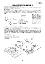


REPLACEMENT OF A/C
(Audio/Control)
HEAD
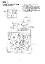
Remove the cassette housing control assembly.
Place the unit in the unloading mode, and
unplug the power cord.
l
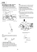
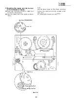
Removal
Loosen the tilt adjusting screw
Remove the azimuth adjusting screw
Remove the
head screw
Unsolder the A/C head
soldered to the A/C
head assembly.
Notes:
After replacement, be sure to perform the
adjustment of the tape drive train (see page
Under any circumstances, avoid touching the
head. Clean the head, if touched with your
finger, with alcohol.
Take care that the azimuth spring does not fly
off when removing the A/C head screw.
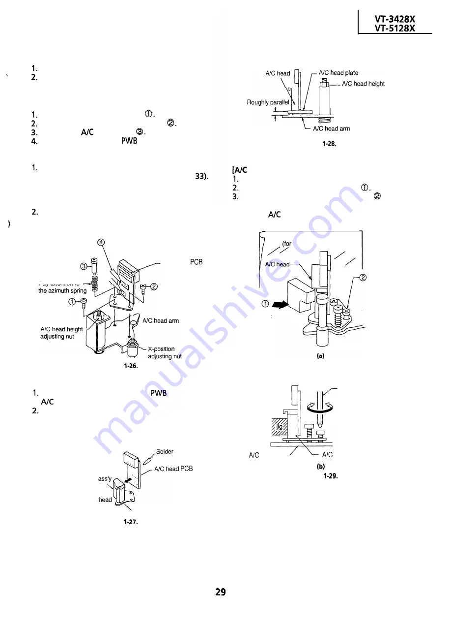
A/C head
Pay attention to
Figure
l
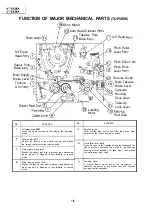
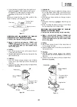
Replacement
Solder the removed A/C head
onto a new
head assembly.
The A/C head assembly is attached so that the
A/C head arm and A/C head plate are roughly
parallel to each other.
New A/C head
Never touch the
adjusting nut
Figure
l
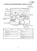
Adjustment
head tilt angle]
Set the mechanism to the loading mode.
Place the A/C head tilt adjusting Jig
Slowly turn the tilt adjusting screw with a
screw driver until there is no gap between the Jig
and the
head.
A piece of white paper
visuality of a gap)
A/C head tilt
adjusting jig
Tilt adjusting
screw
Screw driver
head arm
head
Figure
A/C head plate
Figure
Содержание VT-3428X
Страница 70: ...M 3428X VT 5128X 1c35 1 TDA7056A 1 II TO PWB E Eli 2SC3 198 G 2SC 18 I G I I I I ii i I I 0302 TP1001 70 ...
Страница 74: ...IC35 1 TDA7056A 1 IL TP1001 EXT YYNTRot Gm so1 TO PWB E IEII I o I WT OIIT I 7 I 8 I 9 I 10 I 11 I 12 I 74 ...
Страница 78: ...m 3428X VT 51 28X IF Pack Unit RiWOOl7CEZZ 1 4 11 l e i t 1 I 2 I 3 I 4 I 5 I 6 1 78 ...
Страница 82: ...VT 3428X VT 5128X I AWIO m I Au 10 f X I 7 I 8 I 9 I 10 I 11 I 12 I 82 ...
Страница 86: ...VT 3428X VT 5128X I n SAFETY DEVICE BLOCK DIAGRAM 4L me A rdl a I 8 rie fI I 7 I 8 I 9 I 10 I 11 I 12 I ...
Страница 90: ...VT 3428X VT 51 28X I t 7 I 8 I 9 I 10 I 11 I 12 I ...
Страница 94: ...VT 3428X W 5128X 3 7 I 8 I 9 I 10 I 11 I 12 I 94 ...
Страница 96: ...VT 3428X VT 51 28X TO Y C AUDIO CIRCUIT NCR 21 I I I I 7 I 8 I 9 I 10 I 11 I 12 I 96 ...
Страница 100: ...m 3428X VT 51 28X Wiring Side f r 7 I 8 I 9 I 10 I 11 I 12 1 100 ...
Страница 101: ...n n VCR SECTION H G F E D C B A VT 3428X VT 51 28X 1 lclinch PWB E VCR Unit Wiring Side I i 1 I 2 I 3 I 4 I 5 I 6 101 ...
Страница 102: ...VT 3428X VT 51 28X I 7 I 8 I 9 I 10 I 11 102 1 12 I ...
Страница 103: ...VT 3428X VT 51 28X n l VCR SECTION PWB E VCR Unit Chip Parts Side I i 1 I 2 I 3 I 4 I 5 I 6 c 103 ...
Страница 104: ...VT 3428X I m 5128X 1 7 I 8 I 9 I 10 I 11 I 12 I ...
Страница 123: ...MECHANISM CHASSIS PARTS G F E I i 1 I 2 I 3 I 4 I 5 I 6 I 123 ...
Страница 125: ...CASSETTE HOUSING CONTROL PARTS i T 3428X VT 51 28X 1 I 2 I 3 I 4 I 5 I 6 I 125 ...
Страница 127: ...VT 3428X W 51 28X MODIEL VT 3428X CABINET AND MECHANICAL PARTS 1 I 2 I 3 I 4 I 5 I 6 127 ...
Страница 128: ...W 3428X VT 51 28X I IO 9 0 3 7 128 ...
Страница 129: ...VT 3428X VT 51 28X MODEL VT 5128X CABINET AND MECHANICAL PARTS v m m 1 I 2 I 3 I 4 I 5 I 6 129 ...
Страница 130: ...VT 3428X VT 5128X I 0 I 0 ...
Страница 132: ...MODELS VT 3428X AND VT 51 28X CABINET AND MECHANICAL PARTS I i 1 I 2 I 3 I 4 I 5 I 6 I 132 ...
Страница 136: ...S H A R P TQ0023 S Printed in Japan 0 w s MW KD ...