

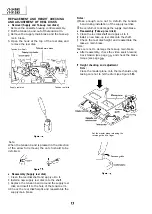


Pinch
Tension gauge
g
Capstan shaft
Tension gauge adapter
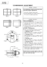
Figure
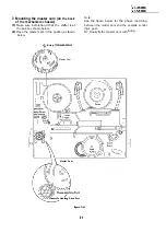
Detach the pinch roller from the capstan shaft.
Set the tension gauge by hooking the tension
gauge adapter onto the pinch roller shaft.
Gradually release the pressure to allow the pinch
roller to touch the capstan shaft. When the
pinch roller just touches the capstan shaft, read
the indication on the gauge.
Check that the reading of the tension gauge is in
the range of
to
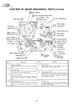
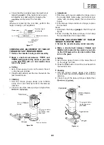
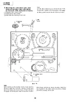
CHECKING AND ADJUSTMENT OF TENSION
POLE POSITION
l
Remove the cassette housing control assembly.
l
Make a short-circuit between
and
both located at the center on your side
on the VCR
with a
ohm resistor. Now
turn on the power.
l
Setting
Open the lid of cassette tape
and hold it
with two pieces of vinyl tapes.
Load the cassette tape into the unit.
Put the weight
on the cassette tape.
Make the adjustment with the beginning of a
E-l tape.
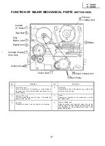
l
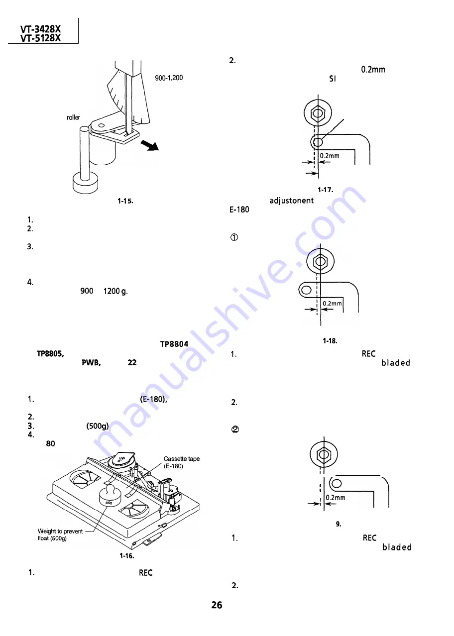
Checking
Figure
Set a cassette tape, press the
button and get
the tape loaded. Now check the tension pole
position.
Visually check to see if the left end of the tension
pole is in alignment with the line
left of
the center line of the roller. Readjust as
required in the following steps.
Tension pole
I
Center line
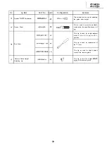
Figure
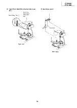
Make the
with the beginning of a
tape.
If the end is at the left from the center line:
Figure
Remove the cassette and press the
button to
make an empty loading. Put a
screwdriver into the tension band positioning
cam and turn it clockwise.
Place the cassette in position and check the
tension pole position.
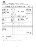
If the end is at the right from the dotted line:
.
I
iI
I
I
0
Figure l-l
Remove the cassette and press the
button to
make an empty loading. Put a
screwdriver into the tension band positioning
cam to turn it counterclockwise.
Place the cassette in position and check the
tension pole position.
Содержание VT-3428X
Страница 70: ...M 3428X VT 5128X 1c35 1 TDA7056A 1 II TO PWB E Eli 2SC3 198 G 2SC 18 I G I I I I ii i I I 0302 TP1001 70 ...
Страница 74: ...IC35 1 TDA7056A 1 IL TP1001 EXT YYNTRot Gm so1 TO PWB E IEII I o I WT OIIT I 7 I 8 I 9 I 10 I 11 I 12 I 74 ...
Страница 78: ...m 3428X VT 51 28X IF Pack Unit RiWOOl7CEZZ 1 4 11 l e i t 1 I 2 I 3 I 4 I 5 I 6 1 78 ...
Страница 82: ...VT 3428X VT 5128X I AWIO m I Au 10 f X I 7 I 8 I 9 I 10 I 11 I 12 I 82 ...
Страница 86: ...VT 3428X VT 5128X I n SAFETY DEVICE BLOCK DIAGRAM 4L me A rdl a I 8 rie fI I 7 I 8 I 9 I 10 I 11 I 12 I ...
Страница 90: ...VT 3428X VT 51 28X I t 7 I 8 I 9 I 10 I 11 I 12 I ...
Страница 94: ...VT 3428X W 5128X 3 7 I 8 I 9 I 10 I 11 I 12 I 94 ...
Страница 96: ...VT 3428X VT 51 28X TO Y C AUDIO CIRCUIT NCR 21 I I I I 7 I 8 I 9 I 10 I 11 I 12 I 96 ...
Страница 100: ...m 3428X VT 51 28X Wiring Side f r 7 I 8 I 9 I 10 I 11 I 12 1 100 ...
Страница 101: ...n n VCR SECTION H G F E D C B A VT 3428X VT 51 28X 1 lclinch PWB E VCR Unit Wiring Side I i 1 I 2 I 3 I 4 I 5 I 6 101 ...
Страница 102: ...VT 3428X VT 51 28X I 7 I 8 I 9 I 10 I 11 102 1 12 I ...
Страница 103: ...VT 3428X VT 51 28X n l VCR SECTION PWB E VCR Unit Chip Parts Side I i 1 I 2 I 3 I 4 I 5 I 6 c 103 ...
Страница 104: ...VT 3428X I m 5128X 1 7 I 8 I 9 I 10 I 11 I 12 I ...
Страница 123: ...MECHANISM CHASSIS PARTS G F E I i 1 I 2 I 3 I 4 I 5 I 6 I 123 ...
Страница 125: ...CASSETTE HOUSING CONTROL PARTS i T 3428X VT 51 28X 1 I 2 I 3 I 4 I 5 I 6 I 125 ...
Страница 127: ...VT 3428X W 51 28X MODIEL VT 3428X CABINET AND MECHANICAL PARTS 1 I 2 I 3 I 4 I 5 I 6 127 ...
Страница 128: ...W 3428X VT 51 28X I IO 9 0 3 7 128 ...
Страница 129: ...VT 3428X VT 51 28X MODEL VT 5128X CABINET AND MECHANICAL PARTS v m m 1 I 2 I 3 I 4 I 5 I 6 129 ...
Страница 130: ...VT 3428X VT 5128X I 0 I 0 ...
Страница 132: ...MODELS VT 3428X AND VT 51 28X CABINET AND MECHANICAL PARTS I i 1 I 2 I 3 I 4 I 5 I 6 I 132 ...
Страница 136: ...S H A R P TQ0023 S Printed in Japan 0 w s MW KD ...