
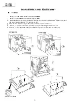
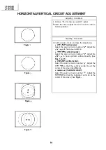


CONVERGENCE ADJUSTMENT
Figure a.
I
I
..I.......... . . . .
.
I
.
.
I
.
.
I
I
.
Figure
Figure
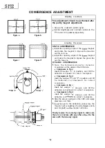
Wedge
Figure
magnet
magnet
CRT neck
.
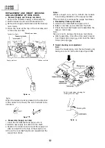
Adjusting Conditions
This adjustment should be performed after
the purity magnet adjustment.
Receive the crosshatch pattern signal.
Set the brightness and contrast controls to the
0 and 1 O/l 0 positions, respectively.
Adjusting Procedures
STATIC CONVERGENCE
Adjust the opening angle of the
magnet
and rotate the magnet to impose the blue line
over the red one.
Adjust the opening angle of the
magnet
and rotate the magnet to impose the green line
over the blue one.
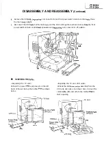
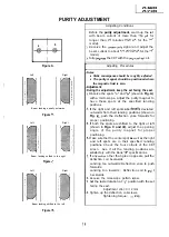
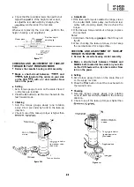
DYNAMIC CONVERGENCE
T a k e t h e f o l l o w i n g s t e p s f o r d y n a m i c
convergence at the edges of the CRT screen.
l
Convergence in Fig a :
Insert the wedge “a” in position, and tilt the
deflection coil upward for correct convergence.
l
Convergence in Fig b :
Insert the wedges
and
in position, and tilt
he deflection coil downward for correct
convergence.
l
Convergence in Fig c :
Insert the wedge
deeper, and tilt the
deflection coil rightward for correct convergence.
l
Convergence in Fig d :
insert the wedge
deeper, and tilt the
deflection coil
for correct convergence.
Stick the above wedges on the CRT, and apply
glass tape over them.
Apply lacquer to the deflection yoke screw, the
magnet unit (consisting of purity,
and
pole magnets)
magnet unit screw.
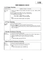
Finally receive the red-only signal to make sure
there is no mixture with any other
Do the
same with the blue-only signal.
Purity magnet
Lacquer
Содержание VT-3428X
Страница 70: ...M 3428X VT 5128X 1c35 1 TDA7056A 1 II TO PWB E Eli 2SC3 198 G 2SC 18 I G I I I I ii i I I 0302 TP1001 70 ...
Страница 74: ...IC35 1 TDA7056A 1 IL TP1001 EXT YYNTRot Gm so1 TO PWB E IEII I o I WT OIIT I 7 I 8 I 9 I 10 I 11 I 12 I 74 ...
Страница 78: ...m 3428X VT 51 28X IF Pack Unit RiWOOl7CEZZ 1 4 11 l e i t 1 I 2 I 3 I 4 I 5 I 6 1 78 ...
Страница 82: ...VT 3428X VT 5128X I AWIO m I Au 10 f X I 7 I 8 I 9 I 10 I 11 I 12 I 82 ...
Страница 86: ...VT 3428X VT 5128X I n SAFETY DEVICE BLOCK DIAGRAM 4L me A rdl a I 8 rie fI I 7 I 8 I 9 I 10 I 11 I 12 I ...
Страница 90: ...VT 3428X VT 51 28X I t 7 I 8 I 9 I 10 I 11 I 12 I ...
Страница 94: ...VT 3428X W 5128X 3 7 I 8 I 9 I 10 I 11 I 12 I 94 ...
Страница 96: ...VT 3428X VT 51 28X TO Y C AUDIO CIRCUIT NCR 21 I I I I 7 I 8 I 9 I 10 I 11 I 12 I 96 ...
Страница 100: ...m 3428X VT 51 28X Wiring Side f r 7 I 8 I 9 I 10 I 11 I 12 1 100 ...
Страница 101: ...n n VCR SECTION H G F E D C B A VT 3428X VT 51 28X 1 lclinch PWB E VCR Unit Wiring Side I i 1 I 2 I 3 I 4 I 5 I 6 101 ...
Страница 102: ...VT 3428X VT 51 28X I 7 I 8 I 9 I 10 I 11 102 1 12 I ...
Страница 103: ...VT 3428X VT 51 28X n l VCR SECTION PWB E VCR Unit Chip Parts Side I i 1 I 2 I 3 I 4 I 5 I 6 c 103 ...
Страница 104: ...VT 3428X I m 5128X 1 7 I 8 I 9 I 10 I 11 I 12 I ...
Страница 123: ...MECHANISM CHASSIS PARTS G F E I i 1 I 2 I 3 I 4 I 5 I 6 I 123 ...
Страница 125: ...CASSETTE HOUSING CONTROL PARTS i T 3428X VT 51 28X 1 I 2 I 3 I 4 I 5 I 6 I 125 ...
Страница 127: ...VT 3428X W 51 28X MODIEL VT 3428X CABINET AND MECHANICAL PARTS 1 I 2 I 3 I 4 I 5 I 6 127 ...
Страница 128: ...W 3428X VT 51 28X I IO 9 0 3 7 128 ...
Страница 129: ...VT 3428X VT 51 28X MODEL VT 5128X CABINET AND MECHANICAL PARTS v m m 1 I 2 I 3 I 4 I 5 I 6 129 ...
Страница 130: ...VT 3428X VT 5128X I 0 I 0 ...
Страница 132: ...MODELS VT 3428X AND VT 51 28X CABINET AND MECHANICAL PARTS I i 1 I 2 I 3 I 4 I 5 I 6 I 132 ...
Страница 136: ...S H A R P TQ0023 S Printed in Japan 0 w s MW KD ...