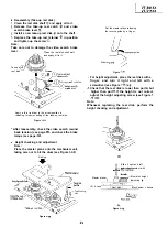
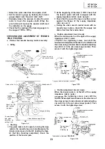
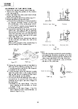

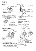
Reassembly
Place the relay gear drive lever in the unloading
state.
Place the relay shifter so that it is in contact with
the reverse guide spring hole in the mechanism
chassis. Release the slow brake lever with a
finger to bring it away from the capstan (in the
direction of arrow). Then place the master cam
so that the D cut-off part of the master cam faces
the direction of arrow.
Turn the master cam somewhat clockwise until
the pinch roller lever’s cam follower goes into
the master cam’s groove (marked with arrow).
Mount the pinch roller lever and then attach the
E ring.
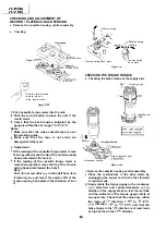
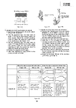
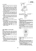
Rotate the master cam by hand to make sure all
the four levers (relay gear drive lever, pinch
roller lever and relay shifter lever) are in the cam
grooves in place.
Mount the loading block. (See page
Notes:
Be careful not to scratch the teeth and grooves
of the master cam.
After installation of the master cam, be sure to
3
rotate the master cam by hand before installing
the loading block.
If the levers are in wrong
position, the master cam and the levers may get
damaged when the motor stares.
Apply specified grease to the master cam’s
grooves and teeth.
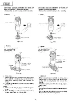
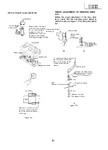
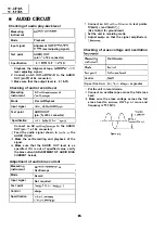
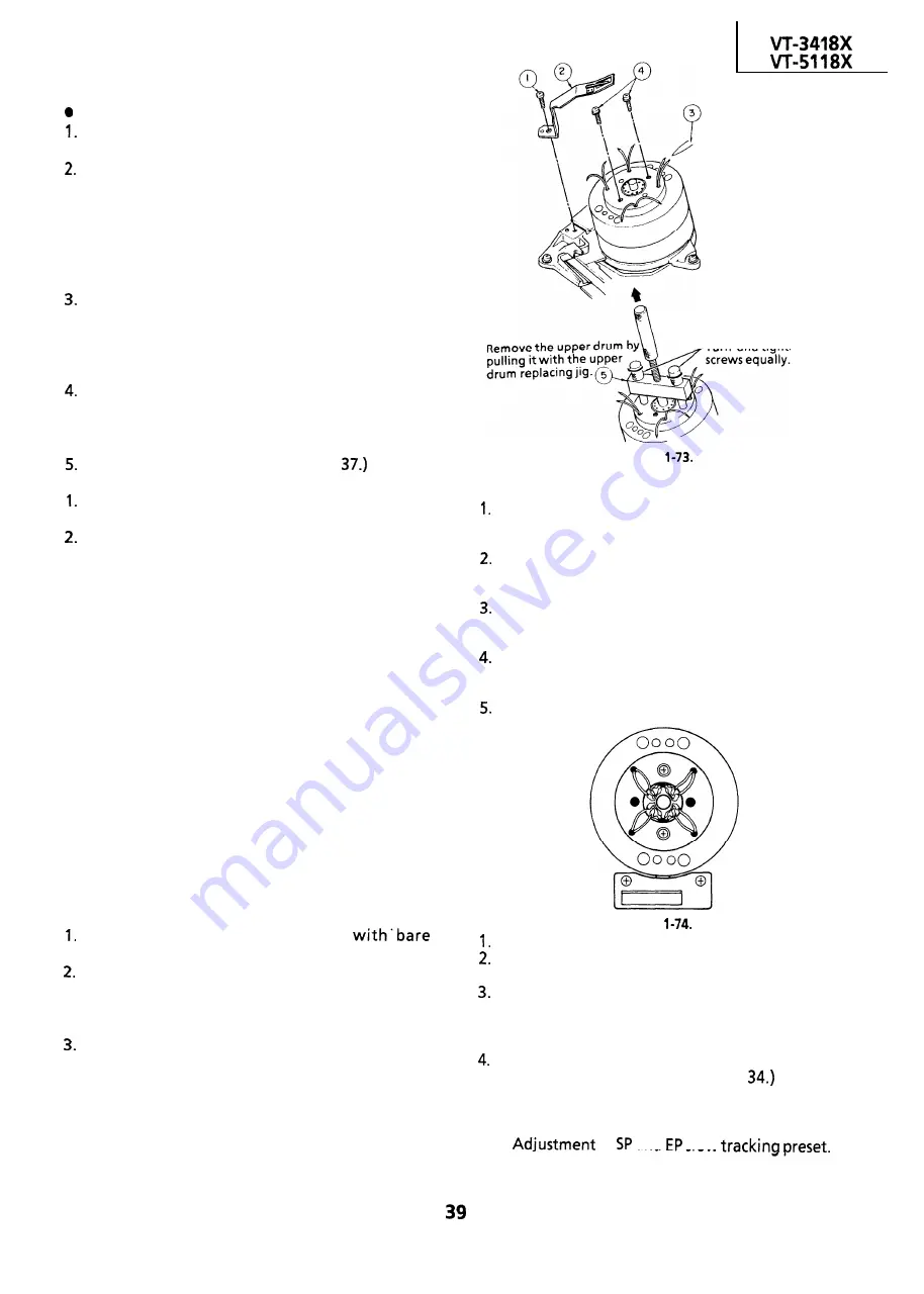
REPLACEMENT OF UPPER DRUM
Note:
The gap between the lower drum and the upper
drum is very accurate, in the order of microns, and
care should be paid to their replacement. Even a
slight amount of foreign material will affect the
accuracy of their reassembly.
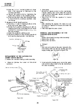
l
Replacement (Follow the order of the indicated
numbers.)
Notes:
Avoid touching the drum surface
hands.
Pull out the upper drum with care so that it may
not be tilted, and replace it with the upper drum
replacing jig using care not to damage the disk
circumference.
Do not hit the screws when tightening them.
Unsolder the leads.
Turn and tighten the
l
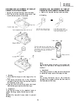
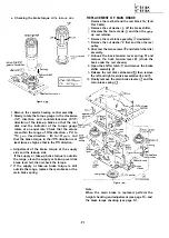
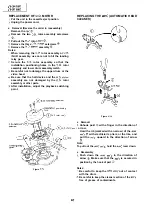
Reassembly
Notes:
Figure
Before setting the drum, check that there are no
scratches or dust on the edge of the surface and
circumference of the disk.
Before setting the drum, check that there are no
scratches or dust on the internal surface and
edge of the surface of the upper drum.
On assembling these parts, insert the upper
drum onto the disk with care, so that the upper
drum is not tilted.
When assembling these parts, do not allow dust
or dirt come between the disk and the upper
drum.
Do not use excessive force when driving in the
screws.
Figure
Set the new drum.
Fasten the upper drum in place with the two
screws.
Solder the leads.
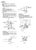
Note:
Soldering should be performed quickly and
carefully without touching adjacent patterns.
After replacement, be sure to check the tape
drive train adjustment (see page
and the
following electric adjustments.
l
Adjustment of the playback switching point.
l
Checking and adjustment of the X-position.
l
of
and
slow
Содержание VT-3418X
Страница 54: ...VT 341 8X VT 51 18X is z 0 Y Y c U T J 2 c 4 54 ...
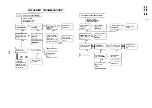
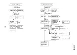
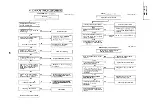
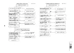
Страница 61: ...VT 341 8X VT 51 18X TROUBLESHOOTING OF TV SECTION I I I I 1 I I I I I I I ___ I iiE I b z 61 ...
Страница 74: ...m 3418X i T 5118X VCJ AV UNIT 7 I 8 I 9 I 10 I 11 I 12 I 74 ...
Страница 76: ...VT 341 8X VT 5118X VCJ AV UNIT I 7 I 8 I 9 I 10 I 11 I 12 1 76 ...
Страница 78: ...PWB B V I D E O CHROMA J U N G L E 7 I 8 I 9 I 10 I 11 I 12 I 78 ...
Страница 80: ...PWE 8 I 1 V I D E O CHROMA JUNGLE hr r I 7 I 8 I 9 I 10 I 11 I 12 I 80 ...
Страница 86: ...VT 341 8X VT 5118X 7 I 8 I 9 I 10 I 11 I 12 I 86 ...
Страница 88: ...rr J I I TUNER w2o1 m ...
Страница 89: ...n 3 30 ...
Страница 90: ...VT 341 8X VT 5118X VCJ AV UNIT DUNTK830 I WEV3 I I I m c I 7 I 8 I 9 I 10 1 11 I 12 I 90 ...
Страница 92: ... VT 341 8X VT 51 18X DUNTK8302WEV 1 DUNTK8303WEV I I 7 I 8 I 9 I 10 I 11 I 12 I 92 ...
Страница 94: ...VT 341 8X VT 5118X DUNTK8302WEV3 DUNTK8303WEV3 7 I 8 I 9 I 10 I 11 I 12 I 94 ...
Страница 97: ... _ _ _ __ D I m I n I t3 I m I n I GI I I 1 ...
Страница 98: ...Memo _ a _ _ 98 ...
Страница 102: ...I REC I w r I I I CAPSTAN FG 7 I 8 I 9 I 10 I 11 I 12 1 102 ...
Страница 106: ...CASSETTE SW REC TIP I ED M I I II DFfwPG I I I I I I I I I I I I ...
Страница 110: ...VT 341 8X I VT 5118X 1 J 7 I 8 I 9 I 10 I 11 I 12 I 110 ...
Страница 112: ...VT 341 8X I T 5118X 1 WAVEFORMS 112 ...
Страница 115: ...SCHEMATIC DIAGRAM n VCR Main Unit r 7 I 1 I 2 I 3 I 4 I 5 I 6 115 ...
Страница 119: ...D I c9 I n I u I m I n I GI I I I ...
Страница 123: ...D I a I n I u I m I n I GI I I I ...
Страница 124: ...11 I 12 I ...
Страница 126: ...J l J I i _ _ _ ___ I _ _ n f f 7 I 8 I 9 I 10 I 11 I 12 126 ...
Страница 152: ...VT 341 8X VT 5118X MECHANISM CHASSIS PARTS 152 ...
Страница 155: ...H G F E D C B A CASSETTE HOUSING CONTROL PARTS 1 I 2 I 3 I 4 I 5 I 6 I 155 ...
Страница 157: ...MECt 1 I 2 I 3 I 4 I 5 I 6 157 ...
Страница 158: ...VT 341 8X VT 51 18X I I 7 I 8 I 9 I 10 I 11 I 12 I 158 ...
Страница 161: ...H G F E D C B A VT 341 8X VT 5118X 1 2 I 3 I 4 I 5 I 6 161 ...
Страница 162: ...VT 341 8X VT 51 18X I I 7 I 8 I 9 I 10 I 11 I 162 12 I ...
Страница 163: ... 1 DEL VT 3418X CABINET AND MECHANICAL PARTS 0 II I L e e m I w F J 1 I 2 I 3 I 4 I 5 I 6 163 ...
Страница 164: ... ...
Страница 169: ...Memo m 169 ...
Страница 170: ...S H A R P T98 19 S Printed in Japan 0 w s MW KD ...