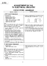

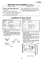
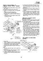
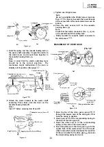
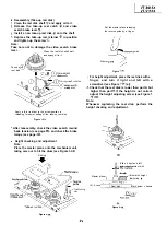
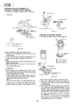
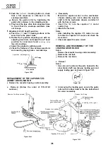

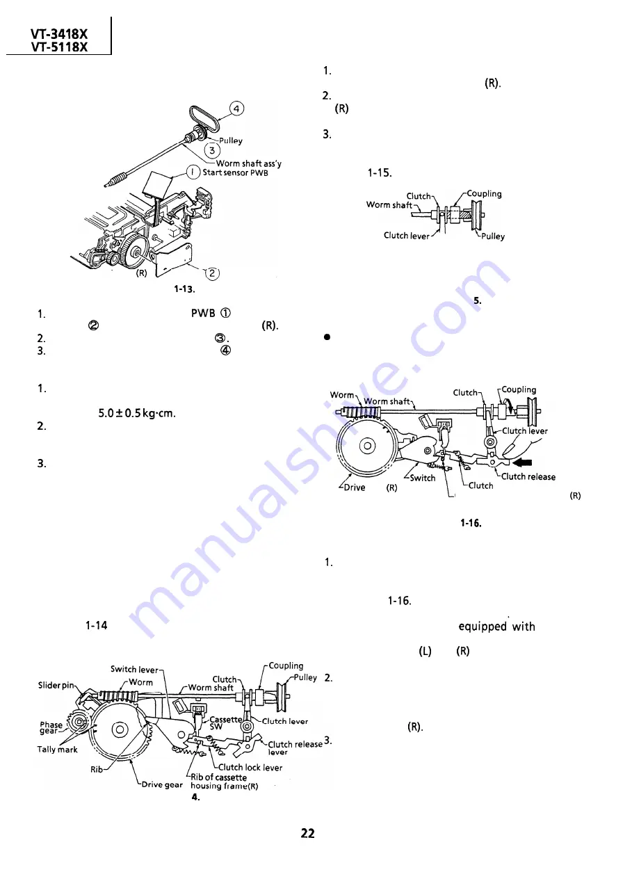
REPLACEMENT OF CASSETTE LOADING
BELT
Cassette housing frame
Worm bracket
Figure
Remove the start sensor
and worm
bracket
from the cassette housing frame
Remove the worm shaft assembly
Replace the cassette loading belt
with a new
one.
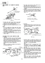
Notes:
Do not over-tighten the B tight screw which holds
the worm bracket in position. The specified
torque is
Make sure that the cassette loading belt is free
from grease.
If stained with grease, clean the
belt with the cleaning liquid.
Perform checking of the clutch switch lever for
proper action.
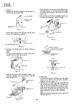
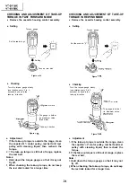
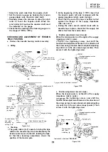
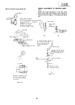
CHECKING THE CLUTCH SWITCH LEVER
l
Checking
Place the mechanism in the cassette eject mode
when removing and attaching the cassette
housing from and to the mechanism chassis.
Make sure enough that each part in the cassette
housing such as the clutch switch lever is in
position. If not, it causes malfunction.
Note:
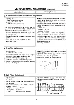
Figure
shows the position of each part in
the cassette eject mode.
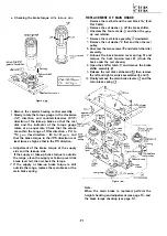
First make sure that the tip of the switch lever is
held at the rib of the drive gear
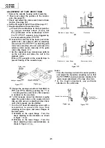
Check that the rib of the cassette housing frame
and the concavity of the clutch lock lever are
engaged.
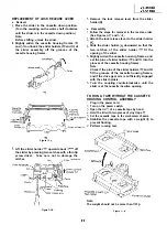
Finally be sure that the relationship between the
clutch lever and the clutch, as well as between
the clutch and the pulley, are correct as in the
Figure
.
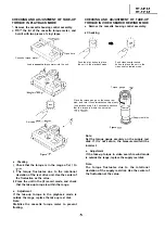
Resetting
Check that the clutch is engaged
with the pulley through the coupling.
Figure l-l
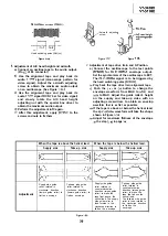
Take the following steps to reset the clutch if it is
unlocked or if the switch lever and the clutch
lock lever are unlocked.
lever
Figure l-l
gear
lever
lock
l e v e r
Rib of cassette housing frame
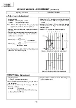
Figure
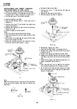
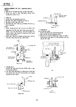
Shift the slider by turning the coupling in the
arrow direction (clockwise) until the slider pin is
at the bottom of the slider groove as shown in
the Figure
(The loading mode)
Note:
Note that the slider is
a lock
mechanism.
Unlock the locks on cassette
housing frames
and
side before shifting
the slider.
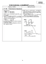
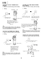
When the position is set as shown in the Figure 4-
16, push the clutch release lever in the direction
of the arrow by hand until the clutch lock lever
becomes tightly locked by the rib of the cassette
housing frame
Then turn the coupling counterclockwise until
the slider reaches the cassette insertion opening
and the reciprocating spring is activated.
Note:
There is no need to unlock the slider when
shifting the slider to the cassette insertion
opening. Just keep shifting the slider.
Содержание VT-3418X
Страница 54: ...VT 341 8X VT 51 18X is z 0 Y Y c U T J 2 c 4 54 ...
Страница 61: ...VT 341 8X VT 51 18X TROUBLESHOOTING OF TV SECTION I I I I 1 I I I I I I I ___ I iiE I b z 61 ...
Страница 74: ...m 3418X i T 5118X VCJ AV UNIT 7 I 8 I 9 I 10 I 11 I 12 I 74 ...
Страница 76: ...VT 341 8X VT 5118X VCJ AV UNIT I 7 I 8 I 9 I 10 I 11 I 12 1 76 ...
Страница 78: ...PWB B V I D E O CHROMA J U N G L E 7 I 8 I 9 I 10 I 11 I 12 I 78 ...
Страница 80: ...PWE 8 I 1 V I D E O CHROMA JUNGLE hr r I 7 I 8 I 9 I 10 I 11 I 12 I 80 ...
Страница 86: ...VT 341 8X VT 5118X 7 I 8 I 9 I 10 I 11 I 12 I 86 ...
Страница 88: ...rr J I I TUNER w2o1 m ...
Страница 89: ...n 3 30 ...
Страница 90: ...VT 341 8X VT 5118X VCJ AV UNIT DUNTK830 I WEV3 I I I m c I 7 I 8 I 9 I 10 1 11 I 12 I 90 ...
Страница 92: ... VT 341 8X VT 51 18X DUNTK8302WEV 1 DUNTK8303WEV I I 7 I 8 I 9 I 10 I 11 I 12 I 92 ...
Страница 94: ...VT 341 8X VT 5118X DUNTK8302WEV3 DUNTK8303WEV3 7 I 8 I 9 I 10 I 11 I 12 I 94 ...
Страница 97: ... _ _ _ __ D I m I n I t3 I m I n I GI I I 1 ...
Страница 98: ...Memo _ a _ _ 98 ...
Страница 102: ...I REC I w r I I I CAPSTAN FG 7 I 8 I 9 I 10 I 11 I 12 1 102 ...
Страница 106: ...CASSETTE SW REC TIP I ED M I I II DFfwPG I I I I I I I I I I I I ...
Страница 110: ...VT 341 8X I VT 5118X 1 J 7 I 8 I 9 I 10 I 11 I 12 I 110 ...
Страница 112: ...VT 341 8X I T 5118X 1 WAVEFORMS 112 ...
Страница 115: ...SCHEMATIC DIAGRAM n VCR Main Unit r 7 I 1 I 2 I 3 I 4 I 5 I 6 115 ...
Страница 119: ...D I c9 I n I u I m I n I GI I I I ...
Страница 123: ...D I a I n I u I m I n I GI I I I ...
Страница 124: ...11 I 12 I ...
Страница 126: ...J l J I i _ _ _ ___ I _ _ n f f 7 I 8 I 9 I 10 I 11 I 12 126 ...
Страница 152: ...VT 341 8X VT 5118X MECHANISM CHASSIS PARTS 152 ...
Страница 155: ...H G F E D C B A CASSETTE HOUSING CONTROL PARTS 1 I 2 I 3 I 4 I 5 I 6 I 155 ...
Страница 157: ...MECt 1 I 2 I 3 I 4 I 5 I 6 157 ...
Страница 158: ...VT 341 8X VT 51 18X I I 7 I 8 I 9 I 10 I 11 I 12 I 158 ...
Страница 161: ...H G F E D C B A VT 341 8X VT 5118X 1 2 I 3 I 4 I 5 I 6 161 ...
Страница 162: ...VT 341 8X VT 51 18X I I 7 I 8 I 9 I 10 I 11 I 162 12 I ...
Страница 163: ... 1 DEL VT 3418X CABINET AND MECHANICAL PARTS 0 II I L e e m I w F J 1 I 2 I 3 I 4 I 5 I 6 163 ...
Страница 164: ... ...
Страница 169: ...Memo m 169 ...
Страница 170: ...S H A R P T98 19 S Printed in Japan 0 w s MW KD ...