
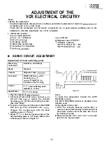
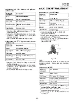
I
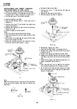
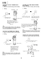
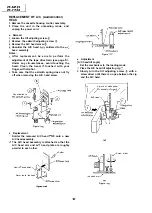
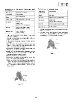
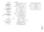
Removal
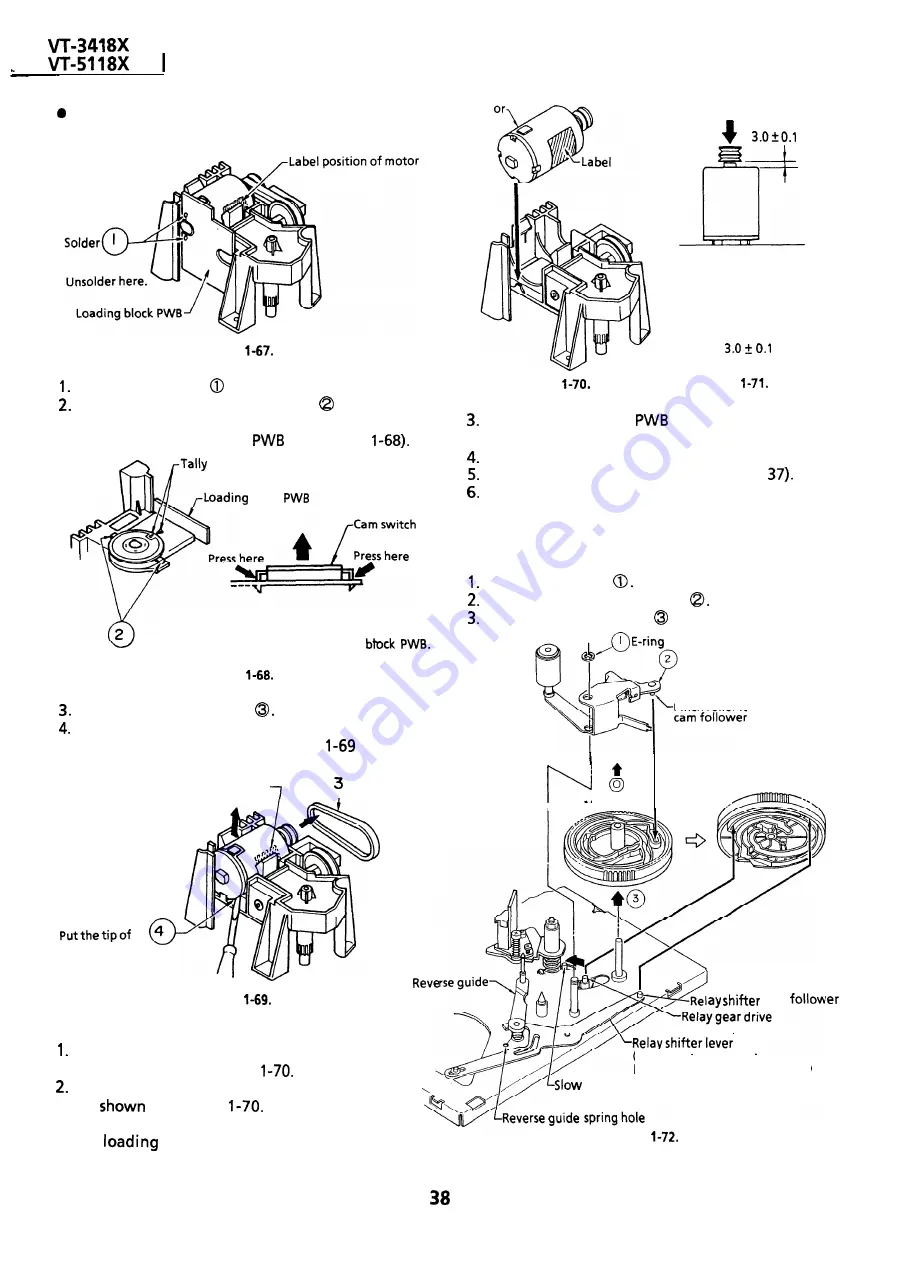
Loading mot
Figure
Unsolder the leads
from the loading motor.
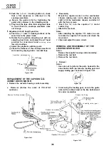
Unlock the left and right catches
of the cam
switch off the loading block. Take out the cam
switch and loading block
(See Figure
marks
block
Pull up the cam switch pressing
the catches. Remove the cam switch
Catches of cam switch
together with the loading
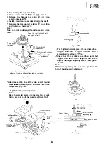
Figure
Take out the loading belt
Pry up the back end of the loading motor with a
screw driver or the like as in Figure
and take
out the motor.
Motor label
Q
Loading belt
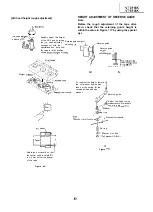
a
screwdriver or
the
like here. Pry UP the
back end of the
loading motor and
take out the motor.
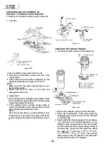
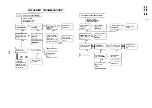
Figure
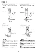
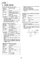
cam
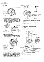
Set the loading block
and the cam switch in
position.
Resolder the leads to the loading motor.
Finally place the loading block (See page
Attach the loading belt.
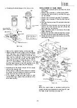
Figure
mm
Note:
When press-fitting the loading
motor pulley, keep the pressure
less than 5 kg, and the gap
between the motor and pulley
should be
mm.
Figure
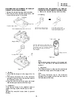
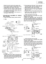
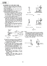
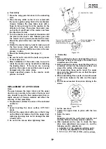
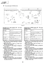
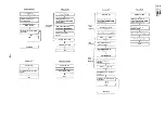
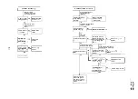
REPLACEMENT OF MASTER CAM
l
Removal
Remove the E ring
Remove the pinch roller lever
Pull out the master cam upward.
Pinch roller lever
Pinch roller lever
I
Master cam
Bottom side of
master
cam
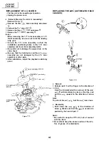
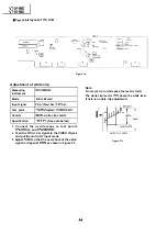
l
Reassembly
Remove the loading motor, and mount a new
loading motor as in Figure
lever cam follower
(Place the relay shifter
lever to the unloading position.)
Place the loading motor so that its label is visible
as
in Figure
Make sure that the
screw hole at the motor shaft, protuberance *on
the
block, and the motor’s back end
marked with the arrow are mated with each
other.
brake lever cam follower
Figure
Содержание VT-3418X
Страница 54: ...VT 341 8X VT 51 18X is z 0 Y Y c U T J 2 c 4 54 ...
Страница 61: ...VT 341 8X VT 51 18X TROUBLESHOOTING OF TV SECTION I I I I 1 I I I I I I I ___ I iiE I b z 61 ...
Страница 74: ...m 3418X i T 5118X VCJ AV UNIT 7 I 8 I 9 I 10 I 11 I 12 I 74 ...
Страница 76: ...VT 341 8X VT 5118X VCJ AV UNIT I 7 I 8 I 9 I 10 I 11 I 12 1 76 ...
Страница 78: ...PWB B V I D E O CHROMA J U N G L E 7 I 8 I 9 I 10 I 11 I 12 I 78 ...
Страница 80: ...PWE 8 I 1 V I D E O CHROMA JUNGLE hr r I 7 I 8 I 9 I 10 I 11 I 12 I 80 ...
Страница 86: ...VT 341 8X VT 5118X 7 I 8 I 9 I 10 I 11 I 12 I 86 ...
Страница 88: ...rr J I I TUNER w2o1 m ...
Страница 89: ...n 3 30 ...
Страница 90: ...VT 341 8X VT 5118X VCJ AV UNIT DUNTK830 I WEV3 I I I m c I 7 I 8 I 9 I 10 1 11 I 12 I 90 ...
Страница 92: ... VT 341 8X VT 51 18X DUNTK8302WEV 1 DUNTK8303WEV I I 7 I 8 I 9 I 10 I 11 I 12 I 92 ...
Страница 94: ...VT 341 8X VT 5118X DUNTK8302WEV3 DUNTK8303WEV3 7 I 8 I 9 I 10 I 11 I 12 I 94 ...
Страница 97: ... _ _ _ __ D I m I n I t3 I m I n I GI I I 1 ...
Страница 98: ...Memo _ a _ _ 98 ...
Страница 102: ...I REC I w r I I I CAPSTAN FG 7 I 8 I 9 I 10 I 11 I 12 1 102 ...
Страница 106: ...CASSETTE SW REC TIP I ED M I I II DFfwPG I I I I I I I I I I I I ...
Страница 110: ...VT 341 8X I VT 5118X 1 J 7 I 8 I 9 I 10 I 11 I 12 I 110 ...
Страница 112: ...VT 341 8X I T 5118X 1 WAVEFORMS 112 ...
Страница 115: ...SCHEMATIC DIAGRAM n VCR Main Unit r 7 I 1 I 2 I 3 I 4 I 5 I 6 115 ...
Страница 119: ...D I c9 I n I u I m I n I GI I I I ...
Страница 123: ...D I a I n I u I m I n I GI I I I ...
Страница 124: ...11 I 12 I ...
Страница 126: ...J l J I i _ _ _ ___ I _ _ n f f 7 I 8 I 9 I 10 I 11 I 12 126 ...
Страница 152: ...VT 341 8X VT 5118X MECHANISM CHASSIS PARTS 152 ...
Страница 155: ...H G F E D C B A CASSETTE HOUSING CONTROL PARTS 1 I 2 I 3 I 4 I 5 I 6 I 155 ...
Страница 157: ...MECt 1 I 2 I 3 I 4 I 5 I 6 157 ...
Страница 158: ...VT 341 8X VT 51 18X I I 7 I 8 I 9 I 10 I 11 I 12 I 158 ...
Страница 161: ...H G F E D C B A VT 341 8X VT 5118X 1 2 I 3 I 4 I 5 I 6 161 ...
Страница 162: ...VT 341 8X VT 51 18X I I 7 I 8 I 9 I 10 I 11 I 162 12 I ...
Страница 163: ... 1 DEL VT 3418X CABINET AND MECHANICAL PARTS 0 II I L e e m I w F J 1 I 2 I 3 I 4 I 5 I 6 163 ...
Страница 164: ... ...
Страница 169: ...Memo m 169 ...
Страница 170: ...S H A R P T98 19 S Printed in Japan 0 w s MW KD ...