UX-B20U/UX-B20C/B25C
5 – 10
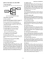
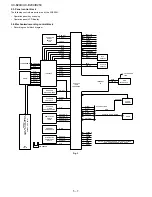
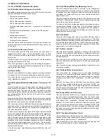
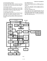
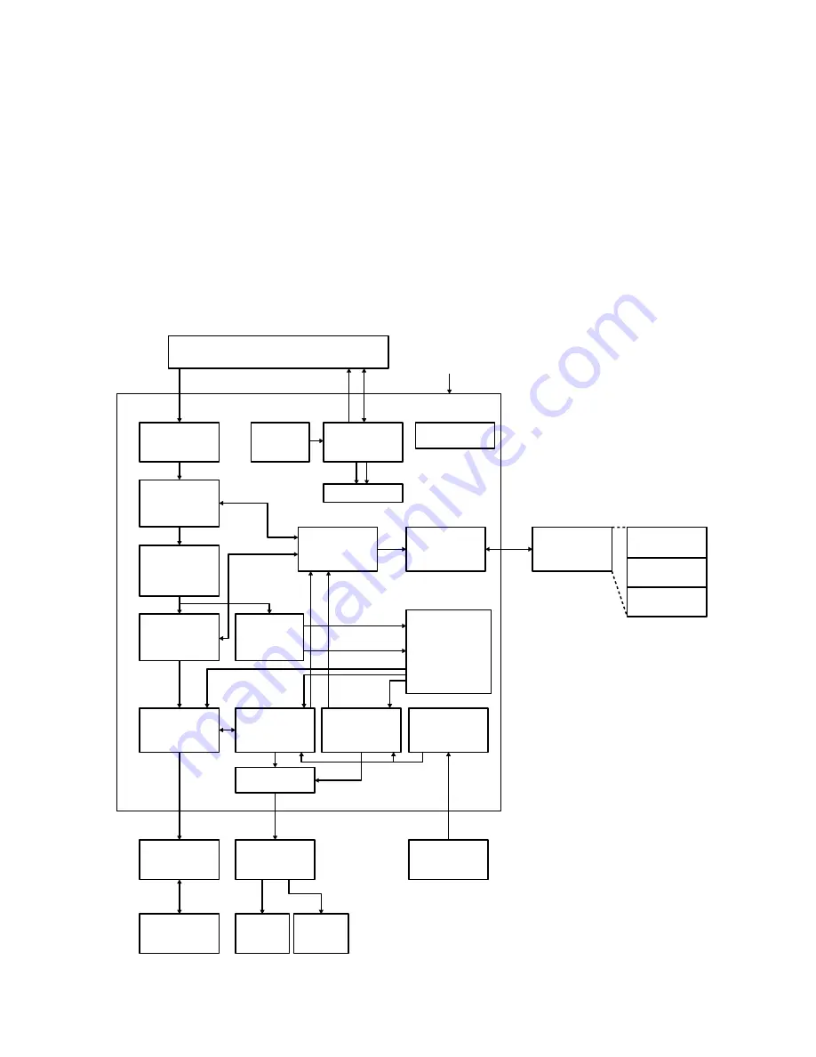
2.6.11 Fax Engine Bus Interface
This interface has a bridging function for connecting the external bus
of Fax Engine LSI and the internal bus of ASIC. Due to the system
clock condition, 1WAIT or more must be set to activate Fax Engine.
2.6.12 Interrupt Controller
This controller logs major causes of interruption in the ASIC and sends
interrupt signals according to the interrupt status of the Fax Engine
firmware (allowed or prohibited). The causes can be cleared or stored.
External interrupt to Fax Engine is generated at L active level.
2.6.13 Memory Access Arbiter
This arbiter arbitrates memory access from each buffer. There are 7
access channels. The arbitration is controlled by priority to maintain
the data transfer rate of the data output channel to the head.
After arbitration, this arbiter notifies the SDRAM controller of memory
addresses and access types and then waits until memory access is
completed.
2.6.14 SDRAM Controller
This controller accesses the memory by controlling the read cycle,
write cycle, and AUTO refresh cycle of a 16-bit wide 16Mbit Synchro-
nous DRAM.
A refresh cycle is automatically inserted by distributed refresh exe-
cuted every 15.6
µ
s (maximum), and when initialization sequence is
performed after reset.
2.6.15 Sensor Detection Circuit
For home position sensor input and paper detection sensor input, this
circuit eliminates noises such as chattering. The detection method is
based on multiple sampling (sequential matching). The sampling clock
is 1.008 MHz and detection time in the register setting should be
approximately between 2
µ
s ~ 65 ms, and can be set for the rising
edge and the falling edge individually.
Serial Data I/F
Fax Engine
Interrupt
Controller
Fax Engine
Bus Interface
Registers
Thunderbolt I/F
Serial Control I/F
Spitfire-LSI
Ink Cartridge
(208 Heaters)
Carrier
Motor
Feed
Motor
Thunderbolt
Sensors
Serial Control I/F
Test etc.
Memory
Bus
x16 SDRAM
16Mbit
PrinterASIC
System Clock
32.256MHz
Fax Engine Bus I/F
Entire
Mechanism
Sequence
Controller
Serial Data
Receiving
Circuit
Input Buffer
384kWord
Enlargement/
Reduction/
Resolution
Conversion Circuit
Split Printing/
White Skip
Measuring Circuit
Print Buffer
512kWord
Spitfire
controller
Carriage Motor
Control Circuit
Feeder Motor
Control Circuit
Memory
Access
Arbiter
SDRAM
Controller
Sensor
Detection
Circuit
Input Buffer
384kWord
Print Buffer
512kWord
Motor table
128kWord
Split Printing indication
White Skip indication
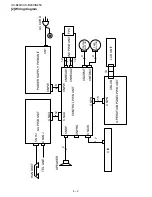
Fig. 5

