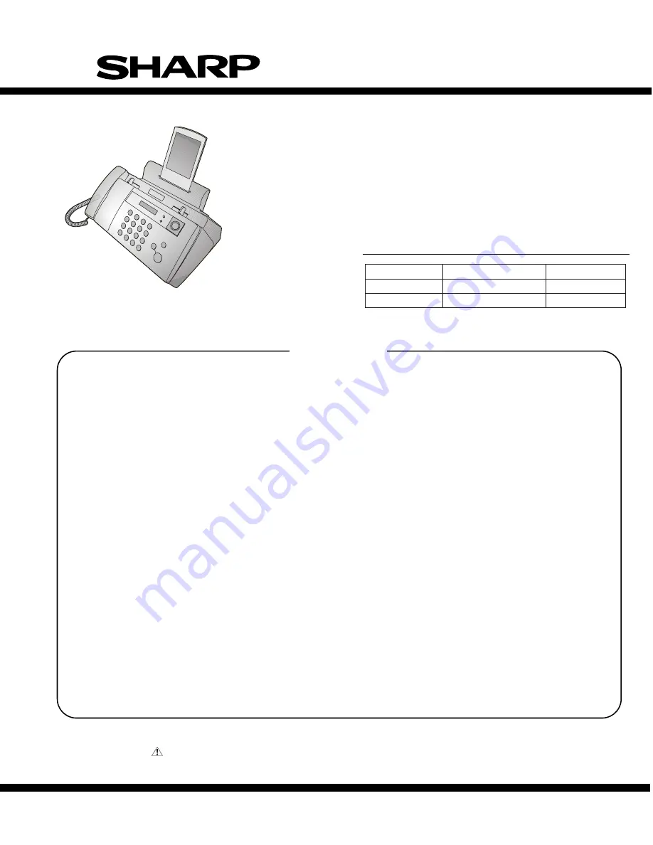
SERVICE MANUAL
MODEL
SELECTION CODE DESTINATION
UX-B20
U
U.S.A.
UX-B20/B25
C
Canada
UX-B20U/UX-B20C/B25C
No. 00ZUXB20U/SME
FACSIMILE
UX-B20
UX-B25
MODEL
SHARP CORPORATION
CONTENTS
Parts marked with "
" are important for maintaining the safety of the set. Be sure to replace these parts with specified ones for
maintaining the safety and performance of the set.
This document has been published to be used
for after sales service only.
The contents are subject to change without notice.
CHAPTER 1. GENERAL DESCRIPTION
[1] Specifications ................................................. 1-1
[2] Operation
panel.............................................. 1-2
[3] Transmittable
documents ............................... 1-3
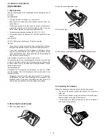
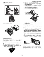
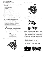
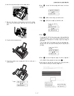
[4] Installation ...................................................... 1-4
[5] Quick setup guide ........................................ 1-10
[6] Quick reference guide .................................. 1-11
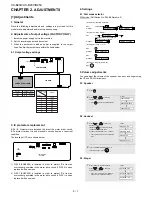
CHAPTER 2. ADJUSTMENTS
[1] Adjustments ................................................... 2-1
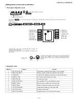
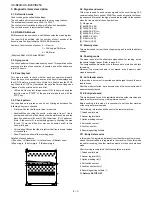
[2] Diagnostics and service soft switch ............... 2-2
[3] Troubleshooting ........................................... 2-23
[4] Error code table............................................ 2-24
CHAPTER 3. MECHANISM BLOCKS
[1] General
description ........................................ 3-1
[2] Ink jet printer .................................................. 3-3
[3] Disassembly and assembly procedures......... 3-6
CHAPTER 4. DIAGRAMS
[1] Block
diagram ................................................ 4-1
[2] Wiring
diagram ............................................... 4-2
[3] Point-to-point
diagram.................................... 4-3
CHAPTER 5. CIRCUIT DESCRIPTION
[1] Circuit
description........................................... 5-1
[2] Circuit description of control PWB ................5-2
[3] Circuit description of LIU PWB ....................5-15
[4] Circuit description of power supply PWB......5-17
[5] Circuit description of CIS unit ......................5-17
CHAPTER 6. CIRCUIT SCHEMATICS AND PARTS
LAYOUT
[1] Control PWB circuit .......................................6-1
[2] LIU PWB circuit ........................................... 6-11
[3] Power Supply PWB circuit...........................6-16
[4] Operation Panel PWB circuit .......................6-18
[5] Ink PWB circuit ............................................6-21
CHAPTER 7. OPERATION FLOWCHART
[1] Protocol .........................................................7-1
[2] Power
on
sequence.......................................7-2
CHAPTER 8. OTHER
[1] Service
tools ..................................................8-1
[2] Changing the record paper size ....................8-4
[3] Rewriting version up the FLASH ROM ..........8-5
Parts Guide
Illustration: UX-B20U


