


9
SX51LF7
SX51LF8
9-1
9-2
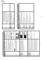
PURITY
ADJUSTMENT
No.
Adjusting point
Adjusting procedure/conditions
W
aveform and others
PURITY
ADJ.
1
.
Receive the GREEN-ONL
Y
signal.
Adjust the
beam current to ~700 µA.
2
.
Degauss the CR
T
enough with the degausing coil.
Note:
Follow the Job Instruction Sheet to ad-
just the magnetic field.
V
ertical Bv:
+0.030 mT (0.30 gauss)
Horizontal
Bh:
+0.020 mT (0.20 gauss)
(Reference: page E-13)
3.
Maintain the purity magnet at the zero magnetic
field and keep the static convergence roughly
adjusted.
4
.
Observe the points a, b as shown in Fig. 4-1
through the microscope.
Adjust the landing to the
A rank requirements.
5.
Orient the raster rotation to 0 eastward.
6.
T
ighten up the deflection coil screws.
»
T
ightening torque: 108 ± 20 N (1
1 ± 2 kgf)
7.
Make sure the CR
T
corners landing meet the
A
rank requirements. If not, stick the magnet sheet
to correct it.
Note:
T
h
is
a
d
ju
s
tment must be done after
warming up the unit for 30 minutes or
longer with a beam current over 700 µA.
Note:
Set the service mode by TP1001 &
TP1002 (short) then press factory proc-
ess R/C RGB key to change to RGB
mono colour mode.
*
For the following colours press R/C RGB key to
change.
1
a
b
A
B
A
30mm
30mm
B
A = B
A = B
Rank "A"
(on the right of the CRT)
Rank "A"
(on the left of the CRT)
Fig. 4-1
Fig. 4-2
Fig. 4-3
*
Press R/C RGB key for 1 sec-
ond in NORMAL MODE, the
colour will change to RGB
mono colour mode.
T
ext Key “ R.G.Cy “ Key can be
directly use to change to other
colours screen.
Signal-colour
screen cleared
GREEN
ONLY
BLUE
ONLY
RED
ONLY
CONVERGENCE ADJUSTMENT
No.
Adjusting point
Adjusting procedure/conditions
W
aveform and others
CONVERGENC
ADJ.
( T
o
be done
after the purity
adjustment.
1.
Receive the "Crosshatch Pattern" signal.
2.
Using the remote controller
, call NORMAL
mode.
Static convergence
1.
T
urn the 4-pole magnet to a proper opening an-
gle in order to superpose the blue and red col-
ours.
2.
T
urn the 6-pole magnet to a proper opening an-
gle in order to superpose the green colour over
the blue and red colours.
Dynamic convergence
1
.
Adjust the convergence on the fringes of the
screen in the following steps.
a
)
Fig. 5-1: Drive the wedge at point "a" and swing
the deflection coil upward.
b)
Fig. 5-2: Drive the wedge at points "b" and "c"
and swing the deflection coil downward.
c)
Fig. 5-3: Drive the "c" wedge deeper and swing
the deflection coil rightward.
d)
Fig. 5-4: Drive the "b" wedge deeper and
swing the deflection coil leftward.
2.
Fix all the wedges on the CR
T
and apply glass
tape over them.
3.
Apply lacquer to the deflection yoke lock screw
,
magnet unit (purity
, 4-pole, 6-pole magnets) and
magnet unit lock screw
.
Finally received the Red-only and Blue-only sig-
nals to make sure there is no other colours on the
screen.
1
RGB
BGR
R
G
B
R
G
B
B
G
R
B
G
R
RGB
BGR
Lacquer
Wedge "a"
Wedge
"b"
Wedge
"c"
About
100Deg
About
100Deg
4-pole magnet
6-pole magnet
CRT neck
20mm
Lacquer
Purity magnet
Fig. 5-1
Fig. 5-2
Fig. 5-3
Fig. 5-4
Fig. 5-5
Fig. 5-6
Содержание SX51LF7
Страница 31: ...31 SX51LF7 SX51LF8 1 2 3 4 5 6 7 8 9 10 A B C D E F G H I J CHASSIS LAYOUT ...
Страница 38: ...42 SX51LF7 SX51LF8 1 2 3 4 5 6 7 8 9 10 A B C D E F G H I J SCHEMATIC DIAGRAM MODEL SX51LF7 CRT Unit ...
Страница 39: ...43 SX51LF7 SX51LF8 1 2 3 4 5 6 7 8 9 10 A B C D E F G H I J SCHEMATIC DIAGRAM MODEL SX51LF8 CRT Unit ...
Страница 43: ...50 SX51LF7 SX51LF8 1 2 3 4 5 6 7 8 9 10 A B C D E F G H I J BLOCK DIAGRAM 2 3 CRT IGR BLOCK SX51LF7 ...
Страница 44: ...51 SX51LF7 SX51LF8 1 2 3 4 5 6 7 8 9 10 A B C D E F G H I J BLOCK DIAGRAM 3 3 NICAM IGR BLOCK SX51LF8 ...


