


8
SX51LF7
SX51LF8
8-1
8-2
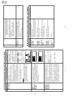
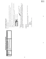
PIF ADJUSTMENT
No.
Adjusting point
Adjusting procedure/conditions
W
aveform and others
T
uner IFT
( PRESET )
1
1
.
Get the tuner ready to receive the CH. E - 9
signal,but with no signal input.
Adjust the PLL data.
2.
Connect the sweep generator's output cable to
the tuner antenna. ( RF SWEEP )
3.
Adjust the sweep generator's to 80dBµV
.
4.
Connect the response lead ( use LOW IMPED-
ANCE probe with wave detector ; see Fig.1 ) to
the tuner's IF output terminal. (
This terminal
must have the probe alone connected ).
5.
Set the RF
AGC to 0 - 6 V with no saturation with
the waveform.
6.
Adjust the tuner IF coil to obtain the waveform as
shown in Fig. 2.
Note:
Be sure to keep the tuner cover in posi-
tion during this adjustment.
RF-AGC
T
AKE OVER
POINT AD-
JUSTMENT
(I2C BUS
CONTROL)
1.
Receive "P
AL
COLOUR BAR" signal.
»
Signal Strength: 54 ± 1 dBµV (75 ohm open)
2.
Connect the oscilloscope to
TP201 (T
uner
’s
AGC
T
erminal) as shown in Fig. 3.
3
.
Call "AGC" mode in service mode.
Adjust the
"AGC" bus data to obtain the
T
uner output pin
drop 0.1V below maximum voltage.
4.
Change the antenna input signal to 63~67dBµV
,
and make sure there is no noise.
5.
T
urn up the input signal to 90~95 dBµV to be sure
that there is no cross modulation beat.
Note: For the 50 ohm signal
strength gauge, when not
using 50/75 impedance
adapter
, signal strength is
52±1dBµV(75 ohm open), in-
stead of 54±1dBµV (75 ohm
open).
Precaution: The loss of using
impedance adapter
.
2
»
Bias box:
About 4.5 V
Oscilloscope
0.1V
TV Set
Bias box
TP201
+
+
—
—
Fig. 3
E-9 CH
P
C
10k
100k
1n60
75ohm
IF OUT
-1.5+/-0.8dB
1000p
1000p
Oscilloscope
Fig.1
Fig.2
SIF (NICAM/IGR)
ADJUSTMENT
No.
Adjusting point
Adjusting procedure/conditions
W
aveform and others
VCO COIL
T2300
1
1.
Receive “P
AL
colour bar” signal.(E-69)
(Set
AFT
ON 855.25MHz frequency).
2.
Connect DC V
oltmater to
TP202 (MAIN BOARD
TEST POINT).
3.
Check and turn
T2300 counter-clockwise (Left)
to 0V and then turn it clockwise (Right) until
TP202
become 5V
.
After that, turn
T2300 counter-clockwise (Left) until
TP202 became 2.5 ± 0.1Vdc.
*
UNIT
BOARD
ADJUSTMENT
Vcc
5V ± 0.1V
IF Input Frequency
38.9MHz ± 0.1V
Adjust
T2300 unit
TP2300 (NICAM BOARD
TEST
POINT) become 2.5 ± 1.0V
Check after assembly NICAM BOARD
T
est point:
TP202 (IN MAIN BORD).
Preset selected receptiion frequency (AFT OFF)
Check V
oltage 2.5 ±
1.0Vdc.
Precaution: The Vcc, fo and other factors are
considered in theunit board of
the 1.0V tolerance which differ
from the adjustment accuracy
.
Содержание SX51LF7
Страница 31: ...31 SX51LF7 SX51LF8 1 2 3 4 5 6 7 8 9 10 A B C D E F G H I J CHASSIS LAYOUT ...
Страница 38: ...42 SX51LF7 SX51LF8 1 2 3 4 5 6 7 8 9 10 A B C D E F G H I J SCHEMATIC DIAGRAM MODEL SX51LF7 CRT Unit ...
Страница 39: ...43 SX51LF7 SX51LF8 1 2 3 4 5 6 7 8 9 10 A B C D E F G H I J SCHEMATIC DIAGRAM MODEL SX51LF8 CRT Unit ...
Страница 43: ...50 SX51LF7 SX51LF8 1 2 3 4 5 6 7 8 9 10 A B C D E F G H I J BLOCK DIAGRAM 2 3 CRT IGR BLOCK SX51LF7 ...
Страница 44: ...51 SX51LF7 SX51LF8 1 2 3 4 5 6 7 8 9 10 A B C D E F G H I J BLOCK DIAGRAM 3 3 NICAM IGR BLOCK SX51LF8 ...


