background image

MX-M200D SIMULATIONS 7-18

25

01

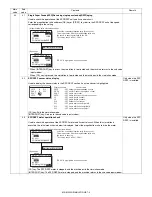
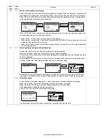
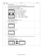
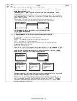
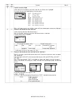
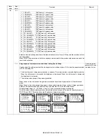
Main motor operation check (Cooling fan motor rotation check)

When [OK] key or [START] key is pressed, the main motor (as well as the duplex motor in the case of the 
duplex model) is rotated for 30 sec.
If the developing unit is installed to save toner consumption at that time, the developing bias, the main 
charger, and the grid are also outputted.
In addition, since laser discharge is required when the motor is stopped, the polygon motor is also operated. 
Check if the developing unit is installed or not. If it is not installed, the previous high voltage is not outputted 
and only the motor is rotated.
After completion of 30sec operation, the machine shifts to the sub code input window.
* This simulation must not be executed with the door open/close switch forcibly turned ON.

After completion of the process, the machine shifts to the sub code input window. 
[CA] key: Exits the simulation mode.
[INTERRUPT] key: Interrupts the output operation, and shifts to the sub code input window. 

02

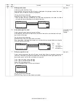
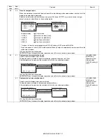
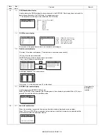
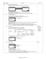
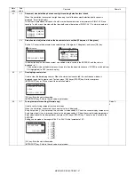
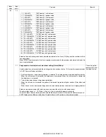
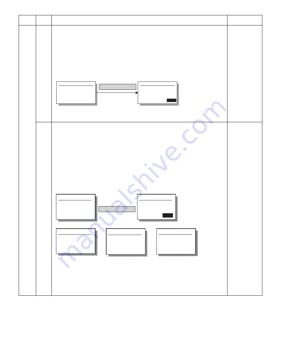
Toner density reference control level setting (automatic development adjustment)

To execute this simulation, perform the following procedures.

[Procedures]

1) Check to confirm that the machine power is turned OFF. Install the DV unit.

2) With the cover open, turn ON the machine power.

3) The machine goes to the SIM25-02 mode. ("Cover open MSG" is displayed. Start LED: OFF.)

4) Close the side cover. (Start LED:ON)

5) Press [OK] key or [START] key.

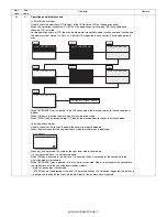
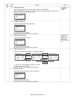
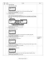
When [OK] key or [START] key is pressed, the main motor rotates for 3 minutes to determine the toner 
sensor reference value and clear the developer rotation time, in addition, the developer counter is cleared.
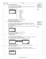
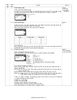
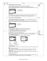
When the procedures are completed normally, the ATC sensor reference value is displayed on the value 
display section. In case of an error, the following screen is displayed.

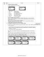
Note:
When the machine is not in the simulation mode, if the front cover is closed and the machine power is turned 
ON, toner may be supplied from the toner cartridge to the developer cartridge. 
Under this state, the toner density reference control level adjustment cannot be performed properly. 
If, therefore, the front cover is closed and the machine power is turned ON when the machine is not in the 
simulation mode, dispose developer, supply new developer, and adjust the toner density reference level.
It takes about 3 minutes to complete the SIM25-02. Never open the front cover or turn OFF the machine 
power during execution of this simulation. 

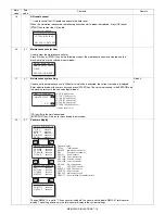
Main 
code

Sub 

code

Contents

Remark

Sim25-1  MAIN MOTOR

PRESS OK KEY

EXEC

Sim25-1  MAIN MOTOR

EXEC

[OK] key or [START] Key

(Execution start window)

(Execution window)

[OK] key or [START] Key

(Execution start)

(Normally completed)

(EL error)

(EU error)

(Executing)

Sim25-2 AutoDv ADJ.


DEVELOPER ADJUST

[nnn]

Sim25-2 AutoDv ADJ.

DEVELOPER ADJUST

PRESS OK KEY   EXEC

EXEC

Sim25-2 AutoDv ADJ.

DEVELOPER ADJUST

COMPLETE

[nnn]

Sim25-2 AutoDv ADJ.

DEVELOPER ADJUST

EU trouble

[nnn]

Sim25-2 AutoDv ADJ.

DEVELOPER ADJUST

EL trouble

[nnn]

Содержание MX-M160

Страница 1: ...SYSTEM MX M200D MX M200DK MX M160D MX M160DK MX M160 As for the content of the MX M200DK MX M160DK refer to the content of the MX M200D MX M160D as long as there is no proviso CODE 00ZMXM200DS1E MX M200D MX M160D MX M160 1 GENERAL 1 1 2 CONFIGURATION 2 1 3 SPECIFICATIONS 3 1 4 CONSUMABLE PARTS 4 1 5 EXTERNAL VIEWS AND INTERNAL STRUCTURES 5 1 6 ADJUSTMENTS 6 1 7 SIMULATIONS 7 1 8 USER PROGRAMS 8 1 ...

Страница 2: ...SETTINGS 1 List of user programs 8 1 2 Using the system settings 8 2 9 TROUBLE CODE LIST 1 Trouble code list 9 1 2 Details of trouble codes 9 1 10 MAINTENANCE 1 Maintenance table 10 1 2 Maintenance display system 10 2 3 Note for replacement of consumable parts 10 2 11 DISASSEMBLY AND ASSEMBLY 1 High voltage section Duplex transport section 11 1 2 Optical section 11 2 3 Fusing section 11 4 4 Paper ...

Страница 3: ...to the switch slot The following cautions must be observed to avoid exposure of the laser beam to your eyes at the time of servicing This laser radiation is not a danger to the skin but when an exact focusing of the laser beam is achieved on the eye s retina there is the danger of spot damage to the retina This means that this machine does not produce hazardous laser radiation The use of controls ...

Страница 4: ... those specified herein may result in hazardous laser radiation exposure The socket outlet shall be installed near the machine and shall be easily accessible C Note for installation place Improper installation may damage the machine Please note the following during initial installation and whenever the machine is moved Caution If the machine is moved from a cool place to a warm place condensation ...

Страница 5: ... static electricity 1 When in transit or storing put the parts in an anti static bag or an anti static case and do not touch them with bare hands 2 When and after removing the parts from an anti static bag case use an earth band as shown below Put an earth band to your arm and connect it to the machine 3 When repairing or replacing an electronic part perform the procedure on an anti static mat ...

Страница 6: ...SING SINGLE PASS FEEDER AR SP10 AR VR7 MX NB10 SINGLE PASS FEEDER DOCUMENT COVER JOB SEPARATOR MX FX10 FACSIMILE EXPANSION KIT NEWORK PRINTING SCANNING EXPANSION KIT Standard for North America only MX M200D MX M160D MX M160 Copy STD STD STD Color scanner STD STD STD SPLC printer STD STD STD PCL printer OPT OPT OPT Fax OPT OPT OPT Network OPT OPT OPT Duplex STD STD N A Sort STD STD STD Shifter 1 ST...

Страница 7: ...T OPT AR VR7 DOCUMENT COVER North South America N A Europe Australia Agency OPT OPT STD AR D34 250 SHEET PAPER FEED UNIT OPT OPT OPT AR D35 2X250 SHEET PAPER FEED UNIT OPT OPT OPT MX TR10 JOB SEPARATOR TRAY KIT OPT OPT OPT MX NB10 NEWORK PRINTING SCANNING EXPANSION KIT OPT OPT OPT MX FX10 FACSIMILE EXPANSION KIT OPT OPT OPT AR SM5 256MB EXPANTION MEMORY BOARD OPT OPT OPT AR MM9 FAX EXPANTION MEMOR...

Страница 8: ...nt size A3 11 X 17 Document reference position Left bottom reference Detection Platen Yes Item 1st tray 2nd tray Bypass tray Paper capacity 250 sheets 250 sheets 100 sheets Paper size detection No Paper size is set with the system setting Paper type setting No No No Heavy papersetting is enabled Paper size changing method The paper guide is set by the user Paper when shipping AB series A4 A4 Size ...

Страница 9: ...ations Writing Binary Toner save mode Set by the user program Void area Lead edge 1 4mm rear edge 4mm or less Total of both sides 6mm or less Image loss 4 0mm or less Paper exit section capacity Face down 250 sheets Full detection Detection of 250 sheets count is for only copy mode When the job separator is installed only detection is available Upper stage 100 sheets or 10 6mm or less Lower stage ...

Страница 10: ...s Writing Binary Memory 64MB Hard disk None Item Content Support platform IBM PC AT compatible machine OS SPLC PCL6 SPDL2 PCL5e PS PPD Rerease method Windows 98 Me No No No No No NT 4 0 SP5 or later No No No No No 2000 Yes Yes Yes Yes Yes CD ROM XP Yes Yes Yes Yes Yes CD ROM XP x64 Yes Yes No Yes Yes Web Server 2003 No Yes Yes Yes Yes CD ROM Server 2003 x64 No Yes No Yes Yes Web Vista Yes Yes Yes ...

Страница 11: ...print On Off Watermark Watermark Top secret Confidential Draft Original Copy Position X 50 50 Y 50 50 Sets to the center position Size 6 300 Angle 90 90 Edit Font name Bold text On Off Italic face On Off Text set It depends on the font name Color density 0 255 Print the first page only On Off Item SPLC Type Flat bed scanner Scan system Document table document feed unit Light source White CCFL Reso...

Страница 12: ... KIT AR 205DM Drum Drum fixing plate x1 x1 50K No Name Product name Content Life Remark 1 Toner cartridge MX 206GT Toner cartridge Toner Net 547g With IC x1 16K Life setting by A4 6 document 2 Developer AR 205LD Developer Net 300g x10 500K 50x10 3 Drum KIT AR 205DM Drum Drum fixing plate x1 x1 50K No Name Product name Content Life Remark 1 Toner cartridge MX 206GT Toner cartridge Toner Net 547g Wi...

Страница 13: ...idge shows the date of production Drum cartridge The lot number printed on the front side flange is composed of 6 digits each digit showing the following content Humidity Temperature Use envi ronment conditions 1 2 3 4 5 6 1 Alphabet Indicates the model conformity code A for this model 2 Number Indicates the end digit of the production year 3 Number or X Y Z Indicates the month of packing X stands...

Страница 14: ...o scan face down here 13 Side cover Open to remove misfed paper 5 Handles Use to move the machine 14 Side cover handle Pull to open the side cover 6 Power switch Press to turn the machine power on and off 15 Bypass tray guides Adjust to the width of the paper when using the bypass tray 7 Center tray Copies and printed pages are output to this tray 16 Bypass tray Special paper heavy paper or transp...

Страница 15: ...tate to remove misfed paper 20 Document feeder tray Place the original s that you wish to scan face up here Up to 40 sheets can be placed 26 Exit area Originals exit the machine here after copying scanning when the SPF is used 21 Original guides Adjust to the size of the originals 27 Photoconductive drum Images are formed on the photoconductive drum Do not touch the photoconductive drum green port...

Страница 16: ...e machine and use the scanner function To use the machine as a network scanner 17 ZOOM key Press to select a reduction or enlargement copy ratio 5 FAX key indicator when the fax option is installed LINE indicator DATA indicator This key is used in fax mode 18 AUTO key Press to have the copy ratio selected automatically 6 FAX STATUS key when the fax option is installed This key is used in fax mode ...

Страница 17: ...id RRS Resist roller rotation control solenoid 10 Bypass tray paper transport clutch MPTC Drives the bypass tray paper transport roller 11 Bypass tray paper feed clutch MPFC Drives the bypass tray paper feed roller 12 Bypass tray paper feed solenoid MPFS Bypass tray paper feed solenoid 13 2nd tray transport clutch CPFC2 Drives the 2nd tray transport roller 14 2nd tray transport solenoid FSOL1 2nd ...

Страница 18: ...close detection 11 2nd tray door paper pass sensor PPD2 2nd tray paper entry detection 12 2nd tray paper empty sensor CSS2 2nd tray paper empty detection 13 Paper in sensor PIN Paper transport detection 14 Tray empty CSS1 Tray paper entry detection 15 Front cover SW DSWF Front cover open detection 16 Power switch MAIN SW Turns ON OFF the main power source 18 Tray full sensor TRAY D Tray full detec...

Страница 19: ...mage scanning 3 Main control PWB Main control PWB 4 2nd tray PWB 2nd tray control 5 High voltage PWB High voltage control 6 Power PWB AC power input DC power control 7 Operation main PWB Operation panel input Display operation panel section control 9 LCD OPE PWB Display and operation panel control 10 IMC2 PWB Electronic sort USB2 0 1 10 7 6 5 3 4 2 9 ...

Страница 20: ... rubber roller 10 Waste toner transport roller Transports waste toner to the waste toner box 11 Drum unit Forms images 12 Transfer charger unit Transfer images on the drum onto paper 13 DUP follower roller Transports paper for duplex 14 Duplex transport roller Transports paper for duplex 15 Resist roller Takes synchronization between the paper lead edge and the image lead edge 16 Bypass tray Bypas...

Страница 21: ...of the doctor plate of the developing unit to insure that it is 18mm If the distance is not within the specified range loosen the fixing screw A of the main pole adjustment plate and move the adjustment plate in the arrow direction to adjust Section Adjustment item Adjustment procedure SIM No A Process section 1 Developing doctor gap adjustment Developing doctor gap adjustment 2 MG roller main pol...

Страница 22: ...tment must be performed 1 Set a scale on the OC table as shown below 2 Make a copy 3 Check the copy output If necessary perform the following adjustment procedures 4 Execute SIM 50 1 5 Set the OC lead edge position set value PHOTO indicator ON to 1 The OC image scanning start position is shifted inside the document edge 6 Set the 1st tray lead edge void adjustment value TEXT indicator ON to 1 The ...

Страница 23: ...int surface lead edge position adjustment in advance and be sure to perform the 2nd print surface lead edge position adjustment and then the lead edge void adjustment in this sequence Adjustment specification Set to S D mode for before execution b SPF image lead edge position adjustment SIM50 6 1 Set a scale on the OC table as shown below Note Since the printed copy is used as a test chart put the...

Страница 24: ...djustment SIM50 10 TEXT 1st tray indicator Adjustment specification e Side edge void area adjustment SIM26 43 Note Before performing this adjustment be sure to check that the paper off center adjustment SIM 50 10 is completed 1 Set a test chart UKOG 0089CSZZ on the document table 2 Select a paper feed port and make two copies Compare the 2nd copy and the test chart If necessary perform the followi...

Страница 25: ... contact with the positioning plate perform the adjustment of 4 4 Loosen the set screw of the scanner drive pulley which is not in contact with No 2 3 mirror base unit positioning plate 5 Without moving the scanner drive pulley shaft manually turn the scanner drive pulley until the positioning plate is brought into contact with No 2 3 mirror base unit then fix the scanner drive pulley 6 Put No 2 3...

Страница 26: ...n adjustment When there is no skew copy in the mirror base scanning direction and there is no horizontal error right angle to the scanning direction the adjustment can be made by adjusting the No 2 3 mirror base unit rail height Before performing this adjustment be sure to perform the horizontal image distortion adjustment in the laser scanner section This adjustment must be performed in the follo...

Страница 27: ...e or original glass Be careful to avoid this 5 Main scanning direction FR direction magnification ratio adjustment SIM 48 1 Note Before performing this adjustment be sure the CCD unit is within specification 1 Put a scale on the original table as shown below 2 Execute SIM 48 1 3 After warm up shading is performed and the current set value of the main scanning direction magnification ratio is displ...

Страница 28: ...ub scanning direction magnification ratio correction value is displayed in two digits on the display section 6 Enter the set value and press the START key The set value is stored and a copy is made 7 Change the mode from the duplex original mode to the simplex original mode TEXT indicator lights up and the current back surface sub scanning direction magnification ratio is displayed in two digits o...

Страница 29: ...rk box 3 Slide the lens unit toward the front side and attach it then execute SIM When the display is 143 or below 1 Remove the table glass 2 Remove the dark box 3 Slide the lens unit toward the rear side and attach it then execute SIM When the lens unit is moved execute the OC main scanning magnification ratio auto adjustment SIM 48 1 1 SIM48 3 and the PF original off center adjustment This adjus...

Страница 30: ...ation check 4 11 Shifter home position check 05 01 Operation panel display check 02 Fusing lamp and cooling fan operation check 03 Copy lamp lighting check 06 01 Paper feed transport solenoid operation check 02 Resist roller solenoid RRS operation check 10 Main cassette pickup roller cleaning 07 01 Warm up display and aging with jam detection 06 Intermittent aging 08 Shifting with warm up display ...

Страница 31: ...ment size is settled 15degrees 20degrees 42 01 Developing counter clear 43 01 Fusing temperature setting Normal copy 12 Standby mode fusing fan rotation setting 13 Paper interval control allow inhibit setting 44 01 Enable Disable setting of toner density control correction 16 Toner density control data check and toner density correction quantity display 34 Transfer current setting 46 01 Copy densi...

Страница 32: ...en in simulation The copy lamp is lighted during scanning CA key Exits the simulation mode INTERRUPT key Returns to the sub code input window C key Input value clear Numeric keys Input of the number of scanning 02 Mirror home positions sensor MHPS status display Used to monitor the mirror home position sensor and display the ON OF status of the sensor on the LCD CA key Exits the simulation mode IN...

Страница 33: ...pped and the machine returns to the sub code input window Only when the SPF RSPF is installed Main code Sub code Contents Remark Sim2 1 SPF AGING 115 100 86 1SIDE 2SIDE OK key or START Key Magnification ratio selection window ZOOM 100 EXEC Sim2 1 SPF AGING 115 100 86 1SIDE 2SIDE Execution window ZOOM 100 EXEC Select the scan magnification ratio drive speed This also accords with the magnification ...

Страница 34: ... of OFF After completion of the process the machine returns to the sub code input window When INTERRUPT key is pressed the machine returns to the sub code input window When CA key is pressed the machine exits the simulation mode Only when the SPF RSPF is installed 03 02 Shifter job separator sensor status display Used to monitor the sensors related to the shifter and the job separator and display ...

Страница 35: ...on before terminating the simulation similarly to the shifter Only when the job separator is installed 11 Shifter home position check Used to check the operations of the shifter HP sensor and the shifter When this simulation is executed the initial menu is displayed By the following key operations the left operation and the right operation of the home position sensor and the shifter can be execute...

Страница 36: ...n panel are properly detected When the machine enters the key input check mode the initial menu is displayed When any key is pressed the value on the right lower side is counted up If a key is pressed once it is not counted again When CA key is pressed for the first time it is counted When it is pressed for the second time the simulation mode is terminated When INTERRUPT key is pressed for the fir...

Страница 37: ...ON of 500ms and OFF of 500ms 20 times When the operation is completed the machine returns to the sub code input window When INTERRUPT key is pressed the machine returns to the sub code input window When CA key is pressed the machine exits the simulation mode Main code Sub code Contents Remark Sim5 2 HT LAMP PRESS OK KEY EXEC Sim5 2 HT LAMP EXEC OK key or START Key Initial window Execution window S...

Страница 38: ...ate is displayed After completion of warm up press CA key to exit the simulation mode allowing normal copy operations The copy mode at that time is the aging mode with 0sec of intermittent aging Canceled by turning off the power or executing a simulation which makes the hardware reset When the interruption is pressed to shift to the input standby window the machine does not enter the aging mode 06...

Страница 39: ...this simulation is executed the following execution start window is displayed When OK key or START key is pressed the main charger is turned on for 30 sec in the grid voltage HIGH mode After completion of the process the machine returns to the sub code input window CA key Exits the simulation mode INTERRUPT key Interrupts output operation and shifts to the sub code input window 03 Main charger out...

Страница 40: ... the output operation and shifts to the sub code input window MX M200D MX M160D only Execution is not allowed when DUPLEX setting is OFF 02 Duplex motor reverse rotation check Used to check the duplex motor reverse rotation The duplex motor is rotated in the reverse direction for 30sec After completion of the process the machine shifts to the sub code input window CA key Exits the simulation mode ...

Страница 41: ...00D MX M160D only Execution is not allowed when DUPLEX setting is OFF Default 50 10 Toner motor operation Used to check the operation of the toner motor When this simulation is executed the following execution start window is displayed Press OK key or START key and the toner motor is rotated for about 30sec After completion of the process the machine shifts to the sub code input window CA key Exit...

Страница 42: ...to SIM22 01 total counter display The setting affects only the total counter display in the system settings Main code Sub code Contents Remark Sim16 TROUBLE CLEAR AER YOU SURE EXEC U2 TROUBLE CLEAR Execution start window Sim20 1 COUNTER CLR AER YOU SURE EXEC MAINTENANCE COUNTER CLEAR Sim21 1 CYCLE SET 4 4 0 5 1 MAINTE CYCLE 0 5K 5 000 sheets 1 7 5K 7 500 sheets 2 10K 10 000 sheets 3 25K 25 000 she...

Страница 43: ...de INTERRUPT key Shifts to the sub code input window key key Switches to another page TRAY2 TRAY4 are displayed only when they are installed Main code Sub code Contents Remark Sim22 3 JAM HIS 1 4 XXXXXXX XXXXXXX XXXXXXX XXXXXXX XXXXXXX XXXXXXX XXXXXXX XXXXXXX Sim22 3 JAM HIS 2 4 XXXXXXX XXXXXXX XXXXXXX XXXXXXX XXXXXXX XXXXXXX XXXXXXX XXXXXXX Kinds of jams and display contents SPPD_ON SPF paper ent...

Страница 44: ... code input window When CA key is pressed the machine exits the simulation mode Only when the SPF RSPF is installed 24 01 Jam total counter clear When this simulation is executed the clear confirmation window is displayed as shown below When OK key or START key is pressed the jam total count and the jam memory are cleared and the machine shifts to the sub code input window Main code Sub code Conte...

Страница 45: ...feed counter data in each paper feed section TRAY2 TRAY4 are displayed only when they are installed CA key Exits the simulation mode INTERRUPT key Shifts to the sub code input window 07 Drum counter clear Used to clear the drum counter and the drum rotating time CA key Exits the simulation mode INTERRUPT key Shifts to the sub code input window Main code Sub code Contents Remark Sim24 2 COUNTER CLR...

Страница 46: ...ts to the sub code input window 14 SPF RSPF jam total counter clear Used to clear the SPF RSPF jam total counter OK key or START key Clears the SPF RSPF jam total counter and shifts to the sub code input window CA key Exits the simulation mode INTERRUPT key Shifts to the sub code input window Only when the SPF RSPF is installed 15 Scanner mode counter clear Used to clear the scanner mode counter O...

Страница 47: ...ose the side cover Start LED ON 5 Press OK key or START key When OK key or START key is pressed the main motor rotates for 3 minutes to determine the toner sensor reference value and clear the developer rotation time in addition the developer counter is cleared When the procedures are completed normally the ATC sensor reference value is displayed on the value display section In case of an error th...

Страница 48: ...tions other than the above this setting is invalid Default 0 Default for destinations other than below 1 Australia New Zealand Philippines 03 Auditor setting Used to set the auditor When the coin vendor mode is selected 1 Sort auto select is OFF 2 For Japan the duplex copy use inhibition setting is ON inhibited 3 When the auditor mode exclusive setting is ON manual paper feed inhibited and the sta...

Страница 49: ... mode When setting is changed the machine exits the simulation mode and performs the hard reset INTERRUPT key Shifts to the sub code input window When setting is changed it is invalid START key Setting contents are saved in the EEPROM and the machine shifts to the code input window When setting is changed the machine does not shift to the code input window When this setting is changed the followin...

Страница 50: ... only during the adjustment simulation Without installing a printer or a FAX machine paper is discharged to the upper stage to check if there is no problem or not If SIM26 01 is set to Job separator not installed paper is discharged to the lower stage regardless of this setting CA key Exits the simulation mode INTERRUPT key Shifts to the sub code input window Default 0 22 Language setting clear Us...

Страница 51: ...n the maintenance counter reaches the life over CA key Exits the simulation mode INTERRUPT key Shifts to the sub code entry menu Default 1 37 Cancel of stop at developer life over Stop or Cancel of stop can be selected when the developer counter reaches the life over CA key Exits the simulation mode INTERRUPT key Shifts to the sub code entry menu Default 1 38 Cancel of stop at drum life over Stop ...

Страница 52: ...the machine shifts to the sub code input window Variation in the adjustment value Setting range is 1 99 When the set value is increased by 1 the timing is increased by 2ms The default 38 of transfer ON timing means 320ms from PS release The default 50 of the transfer OFF timing means304ms from P IN OFF CA key Exits the simulation mode INTERRUPT key Shifts to the sub code input window Default 38 TC...

Страница 53: ...f at that time copying paper discharge is continued with the tray full a paper exit jam may occur To avoid this copying is temporarily stopped by this setting 1 150 sheets when the job separator is installed CA key Exits the simulation mode INTERRUPT key Shifts to the sub code input window Default 1 54 LCD contrast PWM duty setting Used to set the PWM duty brightness at the center value of LCD con...

Страница 54: ...settings If this setting is set to Enable 1 the toner save setting appears in the system settings to allow setting CA key Exits the simulation mode INTERRUPT key Shifts to the sub code input window Default 0 74 Total counter display change setting Used to set whether the scanner counter value is added to the total counter display in the system settings CA key Exits the simulation mode INTERRUPT ke...

Страница 55: ...in the EEPROM The saved value is used as the reference for the following document size detection control The values are displayed in the range of 0 255 0 Black 255 White The value in indicates the adjustment threshold value EXEC is highlighted during execution Main code Sub code Contents Remark Display Corresponding sensor POUT Paper exit sensor DPX DUPLEX sensor PIN Paper entry sensor MBEMP Manua...

Страница 56: ...ey or START key Not to clear press INTERRUPT key or CA key to exit the simulation mode CA key Exits the simulation mode INTERRUPT key Shifts to the sub code input window 43 01 Fusing temperature setting Normal copy Used to set the fusing temperature in normal copy When this simulation is executed the current set value is displayed Every time when key is pressed the set value is increased by 5 C fr...

Страница 57: ... START key is pressed the setting is saved to the EEPROM Descriptions of each correction Print ratio correction In this correction the toner supply interval is determined according to the print ratio to prevent against over toner Note for corrections marked with Since Drip supply and Purge process are simulations for analysis do not set them to 1 Enable If they are set to 1 Enable the toner densit...

Страница 58: ...simulation is executed the list of the setting items and the current set value are displayed Select an item to be changed with key and key and enter the adjustment value with numeric keys The setting range is 1 99 When key or key is pressed the page is changed Enter the adjustment value with numeric keys and press OK key The entered value is saved in the EEPROM and the machine shifts to the copy w...

Страница 59: ... the set value is decreased the gamma is decreased to provide a lower contrast Higher gradation Select an adjustment mode with the arrow keys and enter the set value with numeric keys The adjustment range is 1 99 When key or key is pressed the page is changed The shift amount and the slanting value can be individually set for each of five levels of density for each of TEXT TS and TEXT Therefore th...

Страница 60: ...value on the example 50 is not the default value Main code Sub code Contents Remark 1 1 0 SHIFT TEXT density 1 shift amount 2 1 0 GAMMA TEXT density 1 gamma value 3 2 0 SHIFT TEXT density 2 shift amount 4 2 0 GAMMA TEXT density 2 gamma value 5 3 0 SHIFT TEXT density 3 shift amount 6 3 0 GAMMA TEXT density 3 gamma value 7 4 0 SHIFT TEXT density 4 shift amount 8 4 0 GAMMA TEXT density 4 gamma value ...

Страница 61: ...numeric keys The adjustment range is 1 99 When key or key is pressed the page is changed The shift amount and the slanting value can be individually set for each of five levels of density for each of PHOTO mode error diffusion and dither Therefore there are 20 patterns of adjustment modes The value on the example 50 is not the default value Main code Sub code Contents Remark 1 1 0 SHIFT TEXT densi...

Страница 62: ...HOTO Error diffusion density 4 shift amount 8 ED 4 0 GAMMA PHOTO Error diffusion density 4 gamma value 9 ED 5 0 SHIFT PHOTO Error diffusion density 5 shift amount 10 ED 5 0 GAMMA PHOTO Error diffusion density 5 gamma value 11 DI 1 0 SHIFT PHOTO Dither density 1 shift amount 12 DI 1 0 GAMMA PHOTO Dither density 1 gamma value 13 DI 2 0 SHIFT PHOTO Dither density 2 shift amount 14 DI 2 0 GAMMA PHOTO ...

Страница 63: ...on amount in the SPF RSPF mode Since a slightly darker image is outputted in the SPF RSPF mode compares to the OC mode the difference from the OC mode is corrected with this simulation When therefore the exposure in the OC mode is corrected the SPF RSPF exposure is also changed accordingly Enter a correction value with numeric keys and press OK key The adjustment value is saved in the EEPROM and t...

Страница 64: ...nt set value are displayed Select an item to be changed with key and key and enter a desired value with numeric keys The entered value is saved to the EEPROM The adjustment value is in the range of 0 31 Note When SIM26 06 Destination setting and SIM46 19 Auto exposure mode are changed this setting returns to the default accordingly Default 0 Main code Sub code Contents Remark Sim46 29 GAMMA SET Re...

Страница 65: ...essed instead of OK key the machine shifts to the copy execution window and performs copying Default AE 1 TEXT 1 PHOTO1 1 PHOTO2 1 TEXT TS 1 AE TS 1 Main code Sub code Contents Remark Adjustment item selection window Sim46 31 SHARPNESS 1 AE 2 TEXT 3 PHOTO 1 1 2 0 2 1 1 1 1 Sim46 31 SHARPNESS 4 PHOTO 2 5 TEXT TS 6 AE TS 2 2 0 2 1 1 1 1 Display text Copy mode 1 AE AE mode 2 TEXT TEXT mode 3 PHOTO 1 ...

Страница 66: ...window After completion of copying the machine returns to the adjustment value input window When START key is pressed instead of OK key the machine shifts to the copy execution window and performs copying To adjust the sub scanning magnification ratio on the back of the document shift the window to the copy start window and select Duplex Simplex or Duplex Duplex mode with the DUPLEX key The exposu...

Страница 67: ...Flash Rom write error Common window data 0x05 Flash Rom delete error Boot Flash Rom write error Copy window data 0x06 Flash Rom delete error Program Flash Rom write error Scan window data 0x07 Flash Rom write error Boot Flash Rom write error Print window data 0x08 Flash Rom write error Program Flash Rom write error Fax window data 0x09 Flash Rom LOCK error Boot 0x0A Flash Rom LOCK error Program Da...

Страница 68: ... data size error 0x56 Registration data format error 0x03 LOADER no file 0x57 Registration data items insufficient error 0x04 DWLD no file 0x58 Registration data items overlap error 0x05 BOOT no file 0x61 BOOT data size error 0x06 MAIN no file 0x62 BOOT work sum check error 0x07 FONT download impossible 0x63 BOOT Flash erase error 0x08 Option FLASH connection error 0x64 BOOT Flash write error 0x09...

Страница 69: ...10xR mm Example Set 40 When the value of 5 RRC A is increased by 10 the image loss is decreased by1mm 3 Measure the distance H mm from the paper lead edge to the image print start position Set 1 TRAY1 10xH mm Example Set 50 When the value of 1 TRAY1 is increased by 10 the image lead edge shifts to the paper lead edge by 1mm 4 Set the lead edge void amount to B 50 2 5mm When the value of 4 DEN A is...

Страница 70: ...from the manual paper feed BYPASS tray set the following paper according to the destination specification AB series A3 paper Inch series Double Letter paper The adjustment value is in the range of 1 99 When the adjustment value is increased the output image is shifted to the right When the adjustment value is increased by 1 the image is shifted to the right by about 0 1mm Select an adjustment item...

Страница 71: ...m mode with the arrow keys and enter the set value with numeric keys When OK key is pressed the entered value is saved to the EEPROM and the machine shifts to the copy execution window After completion of copying the machine returns to the adjustment value input window When START key is pressed instead of OK key the machine shifts to the copy execution window and performs copying Default OC 50 SPF...

Страница 72: ...ng the scanning end position with the simulation adjusting the image lead edge position Select an adjustment item mode with the arrow keys and enter the set value with numeric keys When OK key is pressed the entered value is saved to the EEPROM and the machine shifts to the copy execution window After completion of copying the machine returns to the adjustment value input window When START key is ...

Страница 73: ...0 RSPF SIDE2 50 RSPF A5 50 DUPLEX 50 PRE FEED 32 Main code Sub code Contents Remark Sim50 19 DUP R VOID 1 PRV SIDE1 2 PRV SIDE2 3 RRC D 1 99 50 50 50 50 Adjustment item selection window Display text array Adjustment mode 1 PRV SIDE1 Paper rear edge void amount 1st print surface 2 PRV SIDE2 Paper rear edge void amount 2nd print surface 3 RRC D Print start position 2nd print surface Ready to copy S ...

Страница 74: ...F RSPF stop position of the mirror unit in the SPF RSPF copy The scanning position is basically determined by the automatic adjustment It can be also adjusted manually Default 50 Main code Sub code Contents Remark Ready to copy S 100 8 1 2 11 Copy start window Copies in progress S 100 8 1 2 11 Copy execution window Adjustment item selection window Copy start window Copy execution window End of cop...

Страница 75: ... to display the detection level when the lamp of the white plate for shading correction is lighted When the simulation code is entered the initial window is displayed to urge execution Press OK key or START key to start the simulation The contents of the operations are as follows 1 The mirror base unit is shifted to the white plate for shading correction 2 The copy lamp is lighted 3 0 is displayed...

Страница 76: ... the SPF RSPF is installed 64 01 Self print Used to perform printing of one page disregarding the optical system status Also when the print command is issued from the host printing is performed When this simulation is executed warm up is performed and the ready lamp is lighted Since however the optical system is invalid initializing is not performed There are following four self printable patterns...

Страница 77: ... Shifts to the sub code input window Default Lamp brightness 1 Kind of flashing 1 67 50 USB reception speed adjustment Used to set an limitation on the print data reception speed when the USB transfer speed is at full speed When images are disturbed in printing through USB change the setting and try again CA key Exits from the simulation mode INTERRUPT key Shifts to the sub code entry window Defau...

Страница 78: ...ISPLAY TIMEOUT Unchecked LANGUAGE SETTING MESSAGE TIME Short 3sec Normal 6sec Long 9sec KEY TOUCH SOUND Low High Off KEY TOUCH SOUND AT INITIAL POINT Off Check box unchecked KEY PRESS TIME Minimum 0 5 1 0 1 5 2 0sec DISABLE AUTO KEY REPEAT OFF The auto repeat functions DISABLE PAPER SIZE SET OFF Paper size setting can be made ENERGY SAVE AUTO POWER SHUT OFF On Check box is checked AUTO POWER SHUT ...

Страница 79: ...gram that has a checkbox go to step 9 7 Select the desired program with the or key 8 Press the OK key and follow the instructions in the program screen 9 To use another program for the same mode select the desired program with the or key To use a program for a different mode press the BACK key and select the desired mode To exit the system settings press the CA key EXPOSURE COLORMODE PAPE RESOLUT ...

Страница 80: ... trouble Time out 99 Panel language error Auditor NOT READY CH ON None Door open CH Blink None Developing cartridge installed Main code Sub code Details of trouble E1 00 Content IMC PWB communication trouble Detail An abnormality occurs in communication between the MCU PWB and the IMC PWB Cause IMC PWB MCU PWB harness abnormality MCU PWB connector disconnection IMC PWB ROM defect data abnormality ...

Страница 81: ... the MCU PWB 10 Content Shading trouble Black correction Detail The CCD black scan level is abnormal when the shading Cause Improper connection of the CCD unit flat cable CCD unit abnormality MCU PWB abnormality Check and remedy Check connection of the CCD unit flat cable Check the CCD unit Main code Sub code Details of trouble E7 11 Content Shading trouble White correction Detail The CCD white sc...

Страница 82: ...ard communication trouble Protocol Detail A break error occurs in communication between the MCU and the FAX board Cause MCU PWB connector connection failure Garbled data Check and remedy Check connection of the FAX board Replace the FAX board Reset the machine Power OFF ON 81 Content FAX board communication trouble Parity Detail A parity error occurs in communication between the MCU and the FAX bo...

Страница 83: ...sing section jam for winding etc Check the POUT sensor harness Check installation of the fusing unit Use SIM14 to clear the self diag display Main code Sub code Details of trouble L1 00 Content Scanner feed trouble Detail The scanner does not complete feeding in the specified time Cause Mirror unit abnormality The scanner wire is disconnected The origin detection sensor abnormality Mirror motor ha...

Страница 84: ...ode Sub code Details of trouble U9 00 Content Panel board communication trouble Detail Communication trouble with the panel board Cause No command can be sent from the MCU to the panel Check and remedy MCU PWB Panel PWB harness trouble Replace the panel or the MCU PWB Machine reset Power OFF ON 80 Content Panel board communication trouble Protocol Detail An error occurs in communication between MC...

Страница 85: ...eal X X X Toner density sensor X X X X Check the sensor head surface DV side sheet X X X X Optical section Lamp unit Reflector O O O O Mirror O O O No 2 3 mirror unit Mirror O O O Pulley X X X CCD peripheral Lens O O O Glass Table glass O O O O White Plate O O O O Other Drive wire X X X Rail X X X Document cover O O O O LSU Dust proof glass O O O O Paper feed section Multi paper feed section Take ...

Страница 86: ...aining quantity display levels 100 75 50 25 10 LO c Press the Light keys Light and Dark keys to cancel Remaining quantity NEAR EMPTY Approx 50 sheets at Area Coverage 6 EMPTY LED ON Flash Machine Operation allowed Stop Developer Life 50K LED ON at 50K of the developer count Machine Selection is available between Not Stop and Stop by Service Simulation SIM 26 37 Setup If Stop is selected the LED wi...

Страница 87: ...The charger wire must be free from twists or bending Be sure to put the charger wire in the V groove C Duplex transport section No Item 1 High voltage section Duplex transport section 2 Optical section 3 Fusing section 4 Paper exit section 5 MCU 6 Optical frame unit 7 LSU 8 Tray paper feed section Paper transport section 9 Bypass tray section 10 Power section 11 Developing section 12 Process secti...

Страница 88: ...put No 2 3 mirror unit to the positioning plate A Assembly Put the notched surface of wire holder 3 downward tighten temporarily and install Adjustment Main scanning direction distortion balance adjustment C Inverter PWB for copy lamp D Copy lamp No Content A Table glass B Copy lamp unit C Inverter PWB for copy lamp D Copy lamp E Lens unit F Wire G Document detection 1 1 2 3 3 4 4 4 1 A A 2 3 3 1 ...

Страница 89: ...ion and measure the magnification ratio 3 Change the installing position in the horizontal direction to adjust the magnification ratio When the copy image is longer than the original shift to the positive direction When the copy image is shorter than the original shift to the negative direction 1 scale of the scribed line corresponds to 0 34 of magnification ratio If this adjustment is not satisfa...

Страница 90: ...ction that the sponge side A of the thermistor comes in contact with heat roller Check that the thermistor is in contact with the upper heat roller No Contents A Fusing unit B Thermostat C Thermistor D Heater lamp E Upper heat roller F Separation pawl G Lower heat roller H Separation pawl 2 2 2 3 1 1 3 4 3 2 M3 12 2 M3 8 2 M4 8 1 1 1 2 3 2 1 2 A ...

Страница 91: ...x them together Place the fusing harness inside the rib C E Upper heat roller Disassembly There are three pawls on the fusing cover Remove the screws and slide the fusing cover to the right to remove The heater lamp is fixed on the fusing cover with a screw Slide the fusing cover to the front and remove the screw then remove the heater lamp A B 3 1 3 2 1 2 1 3 2 2 1 3 1 2 1 1 2 Grease JFE552 Floil...

Страница 92: ...the fusing front paper guide 3 and the top C of the rib on a line and tighten the screw firmly Except for Taiwan Lower the fusing front paper guide to the bottom of the adjustment width and tighten the screw firmly H Separation pawl 4 Paper exit section A Ozone filter 2 2 1 3 3 1 1 3 2 2 A 4 Grease JFE552 C B For Taiwan Except for Taiwan No Content A Ozone filter B Cooling fan C Paper exit unit D ...

Страница 93: ...EMBLY AND ASSEMBLY 11 7 B Cooling fan C Paper exit unit MX M160D M200D MX M160 D Paper exit sensor duplex sensor A Exit sensor B Duplex sensor 2 2 2 3 3 2 1 2 2 3 3 2 4 2 2 2 2 1 1 2 3 3 1 3 2 5 5 1 1 3 2 1 4 4 6 A B ...

Страница 94: ...udinal direction of the paper exit drive gear long hole B Be sure to insert two ribs C into the groove D G Paper exit interface PWB 5 MCU A MCU disassembly Note When replacing the MCU PWB be sure to replace the EEPROM of the MCU PWB to be replaced 1 2 1 1 2 3 4 5 3 1 1 2 A B D C C 1 1 2 2 3 No Content A MCU 3 3 3 4 1 2 1 1 2 1 3 1 1 1 1 1 1 1 2 1 1 2 2 3 3 3 3 3 3 3 4 ...

Страница 95: ...s Adjustment Image lead edge position adjustment Image left edge position adjustment Paper off center adjustment 8 Tray paper feed section Paper transport section A Middle frame unit No Content A Optical frame unit No Content A LSU unit 2 1 1 1 1 1 1 1 3 2 4 2 2 2 2 1 1 3 3 1 4 2 No Content A Middle frame unit B Drive unit C Solenoid paper feed solenoid resist roller solenoid D Resist roller clutc...

Страница 96: ...n below and avoid the clutch and install C Solenoid paper feed solenoid resist roller solenoid D Resist roller clutch Resist roller E Paper feed clutch Paper feed roller 2 1 1 1 1 2 Grease G 484 Moricote X56020 1 2 2 3 1 2 3 3 3 4 Apply grease FG 40H to the gray area UKOG 0004QSZZ 1 2 Apply grease FG 40H to the gray area UKOG 0004QSZZ ...

Страница 97: ... installing direction of the bypass tray transport roller 6 B Bypass tray paper feed C Bypass tray solenoid When installing the solenoid shift it in the arrow direction and install No Content A Bypass tray transport roller Bypass tray paper feed roller B Bypass tray paper feed C Bypass tray solenoid D Bypass tray transport clutch E Pressure plate unit F Bypass tray paper feed clutch A A A 3 4 5 2 ...

Страница 98: ... Pressure plate unit F Bypass tray paper feed clutch Note Push the lever at the right edge of the multi frame cover to the right upper side and remove it 1 2 3 4 5 Apply grease FG 40H to the gray area UKOG 0004QSZZ 1 2 2 3 2 1 3 1 1 2 A A A 2 2 3 1 1 2 3 4 Apply grease FG 40H to the gray area UKOG 0004QSZZ ...

Страница 99: ...ower section A Power unit B Power fan C High voltage P W B D Power P W B E Power switch No Content A Power unit B Power fan C High voltage P W B D Power P W B E Power switch 1 1 1 1 2 1 1 1 3 2 2 2 2 2 2 2 2 2 2 2 2 2 3 2 1 1 1 2 1 2 2 3 2 2 1 1 ...

Страница 100: ...le position adjustment Note Attach it to fit with the attachment reference when replacing the DV blade No Contents A Developing box B Developing doctor C MG roller 2 3 3 3 4 1 1 2 5 4 3 3 0 0 5 0 0 5 Attaching reference DV blade Mark off line Mark off line reference The DV blade surface must be free from foreign materials Do not touch the DV blade tip It must be free from deflection ...

Страница 101: ...minal section is in contact with the metal section of the cleaning blade 13 Others A Operation P W B No Contents A Drum unit B Main charger unit C Cleaning blade 2 1 1 1 2 No Contents A Operation P W B B Tray interface P W B C 2nd tray paper entry sensor Paper empty sensor D 2nd tray paper feed solenoid Transport solenoid E 2nd tray transport clutch F 2nd tray transport roller G 2nd tray paper fee...

Страница 102: ...or installation When installing engage the hole of the LCD box unit with the positioning pin B Tray interface P W B C 2nd tray paper entry sensor Paper empty sensor 2 3 1 3 3 1 1 positioning pin hole 1 2 1 1 1 1 1 1 1 1 1 1 2 2 2 1 1 3 1 2 3 5 3 4 ...

Страница 103: ...d Transport solenoid E 2nd tray transport clutch F 2nd tray transport roller G 2nd tray paper feed clutch H 2nd tray paper feed roller 1 2 2 1 2 1 Apply grease FG 40H to the gray area UKOG 0004QSZZ 1 1 2 A B 3 A 1 2 Apply grease FG 40H to the gray area UKOG 0004QSZZ 1 2 ...

Страница 104: ...tor J Paper entry sensor K Paper empty sensor L Paper feed roller When removing the paper feed roller operate the paper feed clutch with SIM 6 1 and keep the paper feed roller down as shown in the figure above for operation 1 2 1 2 3 1 1 2 3 1 2 3 1 2 ...

Страница 105: ...nstallation The driver is installed by plug and play B Installation procedure The installation procedure in Windows XP is described as follows The installation procedure in other OS is same procedure as XP basically 1 Machine side Executable by performing the Service Simulation No 49 01 Flash Rom program writing mode A word d appears on the operation panel to denote the download mode status 2 Conn...

Страница 106: ...nd select AR M207 M162 M165 Series on the model selection menu Sample display 4 PC side Confirm that the Simulation Command List tree is displayed on the maintenance program 5 PC side When the message the main body has not got started running is displayed on the lowest area of the figure below after the maintenance program is started up select the File and then Reconnect in the menu bar 6 PC side ...

Страница 107: ...is point NOTE For making a second connection with another machine select the File and Reconnect in the menu bar on the maintenance program at the time of the USB being re connected Repeat the previous procedures from the above 5 Forbidden actions while downloading Important Failure in the download concerned may not allow you to conduct the subsequent download procedures Added care should be taken ...

Страница 108: ... SPFCLH SPFPSOL SPFRSOL Sensor Driver Selector L1 2 W0 1 2 3 SPFCOVER PAPER SPFOPEN SPFOUT SPFMOTOR TM TM MMD PWM 12V 5V 3 3V Power FAN 24V HC151 Image BUS PI Bus Image BUS PO Bus CLON DUPLEX Motor Driver Driver MMRDY SELIN1 2 3 8 8 IMC2 PWB IMC2 PWB OA982 DIMM SOCKET SDRAM Flash ROM ISP1583 USB2 0 High speed ADRS Latch P Bus JTAG Image BUS M Bus 16 FAX_Reset UART Video HSYNC LCD 73dot x 119dot 24...

Страница 109: ...ite B06P VL LF White B02P XL LF White INLET HARNESS 230V ONLY AC SWITCH Dehumidifying heater SWITCH Cassette dehumidifying heater Japn only Only for Japan 1st TRAY OR 2nd TRAY OR MULTI CASSETTE P IN HARNESS PSOL HAND SOLENOID HARNESS PICK UP SOL HANDEMP harness CASSETTE EMP HARNESS CASSETTE SW HARNESS FRONT COVER SWITCH SIDE COVER SWITCH AUDITOR OPTION TONER MOTOR MAIN MOTOR DV UNIT SRU CRUM MCU H...

Страница 110: ...OUT 2 2 POUT 175767 3 CN18 B3B PH K K NC 3 3 DGND 5Vp off 5V CN2 S6B PH K R LF RD GND 4 GP1S58 CPEMPTY CPEMPTY 24V DGND DGND 24V CN8 B3B PH K R LF RD GP1S73 LFTMA JOBS_DLD 1 CN14 B3B PH K S LFTMB NC 2 15778 2 CASETTE LFTMA GND 3 CASETTE N C LFTMB DGND DGND CN9 B4B PH K K LF BK D2X 5V 1 1 5V CN31 B3B PH K K PDPX 2 2 PDPX 15778 2 DRUM NC 3 3 DGND DRUM N C GND 4 GP1S58 DGND DGND D2X 1 2 3 4 5 6 10 11...

Страница 111: ...ND DGND SGND 3 CLON PGND PGND PAPER 4 24VFP YSPF YSPF OS 655233 707 SPFCOVER SPFCOVER SMP 02V NC SPMT1 SPMT1 RSOL SPFRSOL SPFOPEN SPFOPEN 24V1 24V1 SPFPOUT SPFPOUT SMR 02V N CN10 B3B PH K R SELIN1B SELIN1B CN4 B2B PH K S 5V SPFCLH SPFCLH 24V1 MHPS SPFGSOL SPFGSOL GSOL DGND PDOWNB PDOWNB GP1S58 5VFP 5V SPFPAPER SPFPAPER CN7 B3B PH K S 24V1 CN12 B4B PH K S N C 1 OUT_A DF3 3S 2C CN2 B3B PH K K CLH 2 ...

Страница 112: ... K TSHP 04V K SDA_CRUM SDA_CRUM SCL_CRUM SCL_CRUM VCC3 VCC3 DGND DGND CN21 B2B XH A BK B02B PASK 24V 24V HPSOL HPSOL CN002 B04P VL CN25 B3B PH K S 250 250 HEATER L RTH_IN VLR 02V N C N C HEATER L N C DGND HEATER N HEATER N 4 7 14 16 8 1 5 6 23 17 2 3 4 4 1 2 1 15 16 10 11 14 5 1 2 3 4 9 10 6 7 15 4 1 2 3 18 17 1 2 1 1 4 3 2 6 3 7 1 2 2 2 2 1 3 5 6 3 4 7 1 2 1 1 1 2 2 8 1 3 4 11 4 8 9 26 8 21 19 12...

Страница 113: ...DGND DGND LED3 LED3 LEDSI LEDSI LEDCLK LEDCLK LEDLATCH LEDLATCH LEDENABLE LEDENABLE LED1 LED1 3 3V 3 3V DGND DGND CN1 9610S 16C CN3 9610 16B SCAN9 SCAN9 SCAN5 SCAN5 CN28 B3P VH SCAN8 SCAN8 24V SCAN7 SCAN7 N C SENSE6 SENSE6 24V1 DSWS SCAN6 SCAN6 SENSE4 SENSE4 SENSE5 SENSE5 SCAN4 SCAN4 SCAN3 SCAN3 SCAN2 SCAN2 SCAN1 SCAN1 SCAN0 SCAN0 FAXSW FAXSW FAXOPD FAXOPD DGND DGND 16 12 13 14 15 8 9 10 11 4 5 6 ...

Страница 114: ...d LIVE LIVE NEUTRAL 172074 1 White DH L DH L DH N ELP 02V ELR 02VF DH L DH L DH N DH N ELP 02V ELR 02VF ELP 02V ELR 02VF DH L DH L DH N DH N ELP 02V ELR 02VF ELP 02V ELR 02VF DH L DH N ELP 02V ELR 02VF A 1 A 2 A 1 A 2 A 1 A 2 A 2 A 1 A 1 A 2 14 16 13 1 2 3 4 5 6 7 8 1 2 3 4 9 10 11 12 1 2 3 4 5 6 7 8 9 10 11 12 1 2 3 4 5 6 7 8 16 17 10 11 12 13 19 17 14 15 9 2 3 9 4 20 12 18 8 11 10 22 21 5 13 15 ...

Страница 115: ...Y3 SELIN1C PGND PGND DGND DGND PSCL2 FSOL2 PSCL3 FSOL3 24V 24V PSCL1 FSOL1 16 17 18 19 12 13 14 15 8 9 10 11 4 5 6 7 Y2 N C SELIN1C SELIN2C PGND DGND DGND Y1 FSOL2 N C N C PGND 2 3 1 1 2 3 1 1 1 2 1 2 2 2 4 1 13 1 2 2 2 1 1 2 1 2 9 1 2 3 16 11 3 1 2 3 10 2 1 SELIN3C 5Vp off 5Vp off 20 SELIN2C 24V 24V 1 Y1 Y2 N C SELIN1C PGND PGND 14 5 6 7 12 8 13 3 2 FSOL1 PSCL2 15 PSCL1 DGND DGND PSCL2 FSOL2 N C ...

Страница 116: ...rt sensor Transmission type Detects paper transport Paper no empty CN26 3 MCU Sensor PDPX Duplex sensor Transmission type Detects paper transport Paper no empty CN26 7 MCU Sensor LFTHP Job separator home position sensor Job separator home position sensor Home position CN26 19 MCU Sensor TRAY_D Tray full space sensor Transmission type Detects full space of paper tray Paper no empty CN26 18 MCU Sens...

Страница 117: ...ray paper feed solenoid Paper feed solenoid for 4th tray ON CN36 7 MCU Solenoid FSOL3 4th tray transport solenoid Transport solenoid for 4th tray ON CN36 8 MCU Power supply 3 3VIN 3 3V logic power Power CN3 14 MCU Power supply 5VEN 5V energy saving power Power CN3 15 MCU Power supply 5VIN 5V power Power OFF when shutoff CN3 17 MCU Power supply 24VIN 24V power Power OFF when shutoff CN3 19 MCU Powe...

Страница 118: ... Constant voltage Motor MMD Main motor Brushless motor Main motor drive control Drive Stop CN24 4 MCU Motor MMRDY Main motor ready Detects main motor standby Standby Stop CN24 3 MCU Motor TMA_O TMB_O Toner motor Synchronous motor Drives toner motor CN30 MCU Motor JOBS_MT0 JOBS_MT1 JOBS_MT2 JOBS_MT3 Job separator motor driving signal Four phase stepping motor Drives job separator motor dirver TRAY ...

Страница 119: ...bout 220 C which is about 40 C higher than that of conventional lead solder and its soldering capacity is inferior to conventional one it is apt to keep the soldering iron in contact with the PWB for longer time This may cause land separation or may exceed the heat resistive temperature of components Use enough care to separate the soldering iron from the PWB when completion of soldering is confir...

Страница 120: ...sfara vid felaktigt batteribyte Använd samma batterityp eller en ekvivalent typ som rekommenderas av apparattillverkaren Kassera använt batteri enligt fabrikantens instruktion German Achtung Explosionsgefahr bei Verwendung inkorrekter Batterien Als Ersatzbatterien dürfen nur Batterien vom gleichen Typ oder vom Hersteller empfohlene Batterien verwendet werden Entsorgung der gebrauchten Batterien nu...

Страница 121: ...ark or copyright of Microsoft Corporation in the U S A and other countries Windows 95 Windows 98 Windows Me Windows NT 4 0 Windows 2000 Windows XP Windows Vista Windows 2000 Server Windows Server 2003 and Internet Explorer are trademarks or copyrights of Microsoft Corporation in the U S A and other countries IBM and PC AT are trademarks of International Business Machines Corporation Acrobat Reader...

Отзывы: