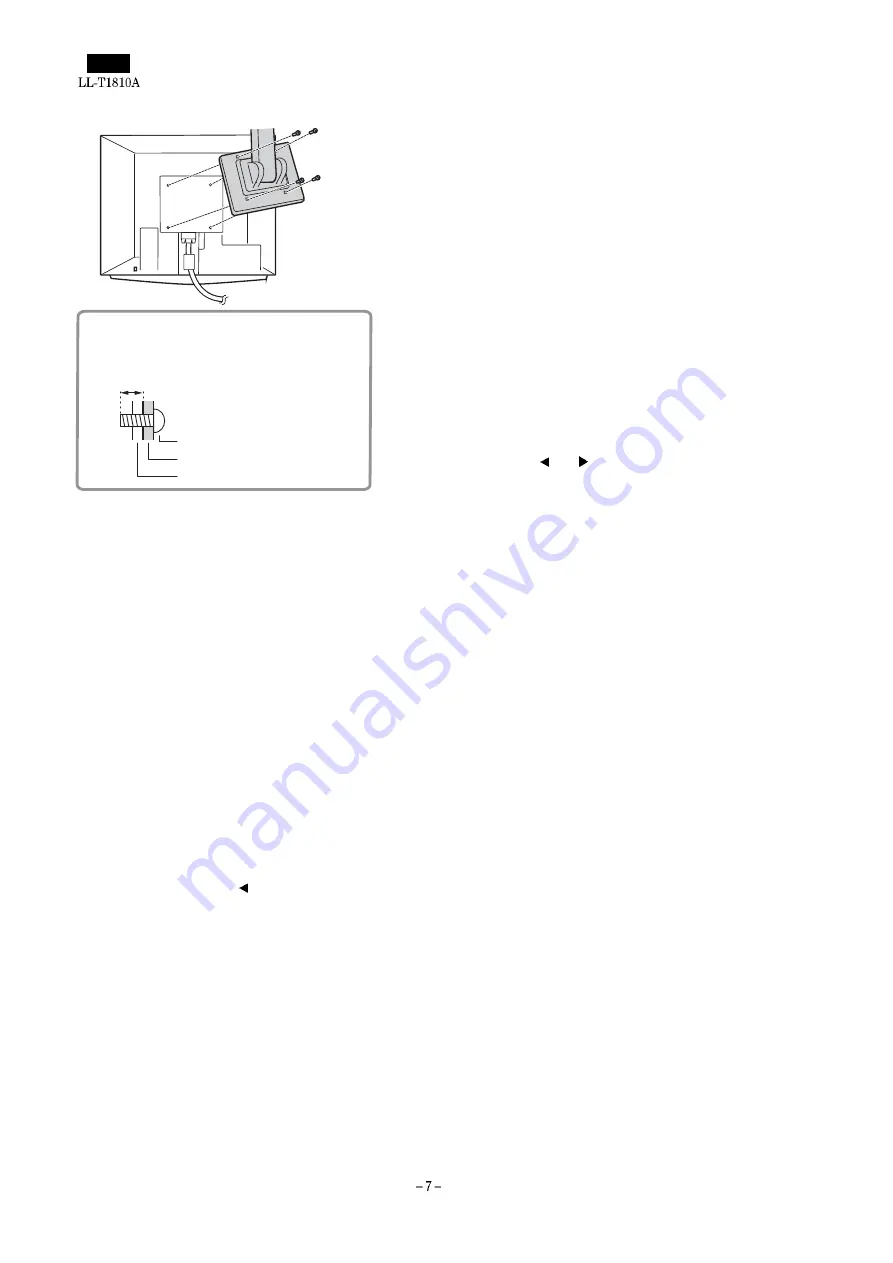
6. Attach the arm to the monitor with the four screws.
[3] ADJUSTING THE SCREEN DISPLAY
If necessary, the screen can be adjusted as follows.
Automatic screen adjustment
The CLOCK, PHASE, H-POS (horizontal positioning) and V-POS
(vertical positioning) functions can be adjusted automatically.
Adjustment of backlight
Brightness of backlight can be adjusted.
Manual adjustment
Fine adjustments can be made using the On Screen Display (OSD)
Menu.
Note: All adjustments will be saved even after turning the power off.
■
Useful functions and tips
Resetting MENU 1 (ADJUSTMENT)
MENU 1 (ADJUSTMENT) values can be returned to their original
ex-factory values in one command.
1. Turn on the monitor power.
2. Press the MENU button and the button simultaneously. When
[RESET] appears on the screen, the reset is complete.
■
Resetting all adjustment values
All adjustment values can be returned to their original ex-factory val-
ues in one command.
1. Turn off the monitor power.
2. Press the MENU button and the SELECT button simultaneously,
and while doing this press the power button (i.e. turn the power
on). When [ALL RESET] appears on the screen, the reset is com-
plete.
Notes:
•
While ALL RESET is displayed, the control buttons are dis-
abled.
•
It is not possible to reset values when the adjustment lock is
in place. Remove the adjustment lock before attempting to
operate control buttons.
■
Adjustment lock function
By disabling the control buttons (i.e. setting the lock) any attempted
changes to adjusted values will be voided.
1. Turn off the monitor power.
2. While pressing the MENU button, press the power button (i.e. turn
the power on). This will set the lock. (When this appears on the
screen, the lock is in place.)
Removing the lock
If the lock is in place and the above-mentioned command is repeated,
the lock will be removed.
Note: When the lock is in place, all buttons other than the power
button are disabled.
■
Choosing a message language
Messages displayed on the screen and OSD Menu contents can be
changed to the following languages.
Dutch, English, French, German, Spanish, Italian, Swedish.
1. Turn off the monitor.
2. Pressing the and buttons simultaneously, press the power
button (i.e. turn the power on).
The Language Selection Menu (LANGUAGE) will be displayed on
the screen.
3. Use the SELECT button to choose a language.
4. Press the MENU button.
The setting is complete. From now, messages and adjustment
menus will be displayed in the chosen language.
AUTOMATIC SCREEN ADJUSTMENT
Options in MENU 1 (ADJUSTMENT) can be adjusted automatically
(CLOCK, PHASE, H-POS, V-POS).
Note:
When setting up the monitor or a connected computer for the first
time, connecting an additional computer or after having changed an
aspect of the current system, perform an automatic screen adjust-
ment before use
■
Automatic adjustment screen display
To perform an automatic adjustment, first display an image that
makes the entire screen very bright. If you are using Windows, you
can also use the Adjustment Pattern on the accompanying Monitor
Settings Adjustment Disk for Windows.
Displaying the Adjustment Pattern (for Windows)
This explanation is for Windows 95/98/2000, and assumes that the
floppy disk drive is [A drive].
Note: If the floppy disk drive of your computer is not "A drive", please
read the below substituting the floppy disk drive you are using
in place of "A drive" or "A".
1. Place the Monitor Settings Adjustment Disk (provided) into the
computer’s A drive.
2. Open [My Computer] and select [3 Floppy (A:)]. If using Windows
3.1, open [File Manager] and choose "A drive".
3. Double click on [Adj_uty.exe] to run the Adjustment Program. The
Adjustment Pattern will appear.
8~10mm
The screws used to attach the arm should be M4 screws
with a length of 8 mm ~ 10 mm protruding from the surface
to be attached.
Using any other kind of screw may lead to the monitor
falling off or damage to the internal part of the monitor
Screw used to attach arm
Arm
Part of monitor to which arm is attached
Содержание LL-T1810A
Страница 21: ...IC terminal diagram 1 3 ...
Страница 22: ...IC terminal diagram 2 3 ...
Страница 23: ...IC terminal diagram 3 3 ...
Страница 34: ...DC JACK PWB 1 1 ...
Страница 36: ...D sub PWB 1 1 ...
Страница 37: ...USB PWB 1 1 ...
Страница 38: ...Main PWB front surface CHAPTER 7 PARTS LAYOUT Symbol PartsCod ...
Страница 39: ...Main PWB rear surface ...


