The power LED
Notes:
•
Depending on the computer or OS, it may be necessary to
use the computer to install monitor set-up information. If so,
follow the steps below to install the monitor set-up informa-
tion.
•
When setting up the monitor or a connected computer for
the first time, connecting an additional computer or after
having changed an aspect of the current system, perform
an automatic screen adjustment before use.
CHANGING BETWEEN INPUT TERMINALS
(INPUT 1
2)
When connected to two computers, use the INPUT button to switch
between input signal terminals (i.e. to choose which computer’s
screen you want displayed.)
TURNING THE POWER OFF
CAUTION!
Do not leave the monitor in contact with rubber or plastic items for
long periods of time as this could lead to color change or change in
shape.
[2] INSTRUCTIONS FOR ATTACHING A
VESA COMPLIANT ARM
An arm or stand based on the VESA standard (purchased separately)
can be attached to the monitor.
Procurement of the arm or stand is at the customer’s discretion.
Arms or stands able to be used
Attachments must satisfy the following.
Compatible with the VESA standard
Have a gap of at least 100 mm x 100 mm between the screw holes
on the section to be attached
Not be likely to fall off or break off after being attached to the
monitor.
How to attach the arm or stand
Note: While following these instructions, please also refer to the in-
stallation instructions in the operation manual included with the
arm or stand
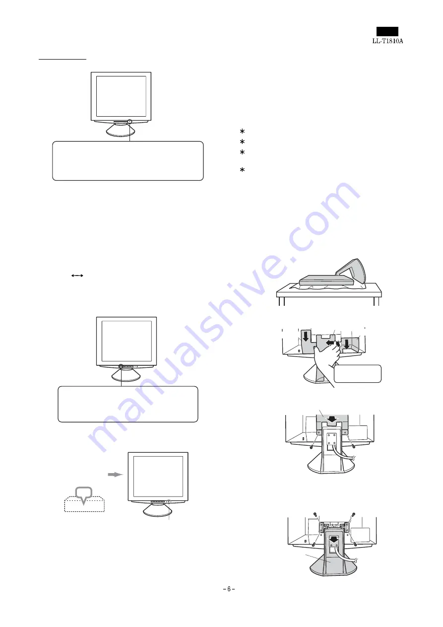
1. Spread out a soft cloth on a suitable horizontal surface.
2. Being careful not to damage the monitor, gently lay the monitor on
it display-side down.
3. Remove the stand cover and the covers to the left and to the right.
4. Remove the two screws, and remove the cover.
5. Remove the four screws and then remove the stand from the
monitor.
Power LED
Green light: In use
Orange light: Power saving mode or signal
failure
Lamp off: Power OFF
INPUT button
Pushing this button switches between input
signal terminals, so that the screen changes to
display any of the machines connected.
OFF
Turn off device to
which monitor is
connected
Turn monitor off
Press power button
(Rear view)
Cover
Cover
Stand cover
Lift one side
Cover
Two screws
Four screws
Stand
Содержание LL-T1810A
Страница 21: ...IC terminal diagram 1 3 ...
Страница 22: ...IC terminal diagram 2 3 ...
Страница 23: ...IC terminal diagram 3 3 ...
Страница 34: ...DC JACK PWB 1 1 ...
Страница 36: ...D sub PWB 1 1 ...
Страница 37: ...USB PWB 1 1 ...
Страница 38: ...Main PWB front surface CHAPTER 7 PARTS LAYOUT Symbol PartsCod ...
Страница 39: ...Main PWB rear surface ...


