LC-90LE657U
6 – 17
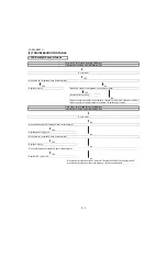
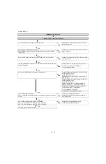
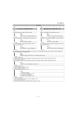
No audio (2)
[PC analog audio input] INPUT-8 No audio.
[HDMI analog audio input] INPUT-2 No audio.
Is INPUT-8 selected on the input select menu screen?
Is INPUT-2 selected on the input select menu screen?
YES
NO
YES
NO
Refer to “: No external input video [INPUT-8]”.
Refer to “: No external input video [INPUT-2]”.
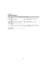
Is the audio output selected for “VARIABLE” on the menu screen?
Is the audio output selected for “VARIABLE” on the menu screen?
YES
NO
YES
NO
Set the audio output to “FIXED”.
Set the audio output to “FIXED”.
Is the “Terminal Setting” - “Audio select” selected for “Video +
Audio” on the menu screen?
Is the “Terminal Setting” - “Audio select” selected for “Video + Ana-
log” on the menu screen?
YES
NO
YES
NO
Set the HDMI audio output to "Video+Audio".
Set the HDMI audio output to "HDMI+Analog".
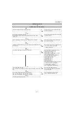
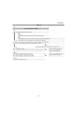
Does the digital audio signal come from pins(AR11/AP11/AN9)(CPU_AOBCK/AOLRCK/AOSDATA0) of IC3301(CPU) to pins(6/7/5)(SP_BCLK/
SP_LRCLK/SP_DATA) of IC1703(Audio DSP)?
YES
NO
Check the line between IC3301 and IC1703 and their peripheral circuits.
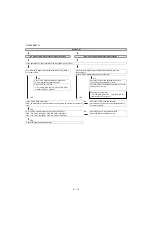
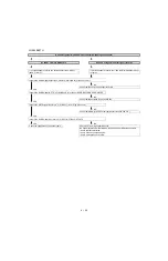
• About the L/R Speakers.
Does the digital audio signal come from pins (30/21/26/27) of IC1703 (Audio DSP) to pin (5/7/8/6) of IC1902 (AMP for L/R)?
• About the Subwoofer speaker.
Does the digital audio signal come from pins (30/21/26/28) of IC1703 (Audio DSP) to pin (5/7/8/6) of IC1901 (AMP for SW)?
YES
NO
Check IC1703 and its paripheral circuits.(X1701, etc.)
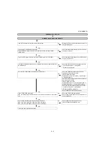
• About the L/R Speakers.
Is the audio output from IC1902 as specified?
• About the Subwoofer Speaker.
Is the audio output from IC1901 as specified?
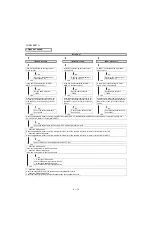
YES
NO
• About the L/R Speakers.
Check IC1902 and its peripheral circuits.
• About the Subwoofer Speaker.
Check IC1901 and its peripheral circuits.
• About the L/R Speakers.
Check the connector (P1903) L/R speakers and their peripheral circuits.
• About the Subwoofer Speaker.
Check the connector (P1904), subwoofer speaker and their peripheral circuits.
Содержание LC-90LE657U
Страница 6: ...LC 90LE657U 1 1 LC 90LE657U Service Manual CHAPTER 1 SPECIFICATIONS 1 SPECIFICATIONS ...
Страница 7: ...LC 90LE657U 2 1 LC 90LE657U Service Manual CHAPTER 2 OPERATION MANUAL 1 OPERATION MANUAL ...
Страница 8: ...LC 90LE657U 2 2 ...
Страница 9: ...LC 90LE657U 2 3 ...
Страница 10: ...LC 90LE657U 3 1 LC 90LE657U Service Manual CHAPTER 3 DIMENSIONS 1 DIMENSIONS ...
Страница 66: ...LC 90LE657U 7 3 MEMO ...
Страница 68: ...LC 90LE657U 8 2 2 SYSTEM BLOCK DIAGRAM 1 2 3 10 9 7 6 5 4 8 J A B C D E F G H I 13 11 19 18 16 15 14 12 17 ...
Страница 75: ...LC 90LE657U ...
Страница 81: ...LC 90LE657U 1 3 1 2 3 10 9 7 6 5 4 8 J A B C D E F G H I 13 11 19 18 16 15 14 12 17 MAIN Unit Side B ...
Страница 85: ...LC 90LE657U 1 7 1 2 3 10 9 7 6 5 4 8 J A B C D E F G H I 13 11 19 18 16 15 14 12 17 LCD CONTROL Unit Side B ...
Страница 94: ...LC 90LE657U 2 8 1 2 3 10 9 7 6 5 4 8 J A B C D E F G H I 13 11 19 18 16 15 14 12 17 MAIN Unit 7 ...
Страница 100: ...LC 90LE657U 2 14 1 2 3 10 9 7 6 5 4 8 J A B C D E F G H I 13 11 19 18 16 15 14 12 17 LCD CONTROL Unit 2 ...
Страница 101: ...LC 90LE657U 2 15 1 2 3 10 9 7 6 5 4 8 J A B C D E F G H I 13 11 19 18 16 15 14 12 17 LCD CONTROL Unit 3 ...
Страница 102: ...LC 90LE657U 2 16 1 2 3 10 9 7 6 5 4 8 J A B C D E F G H I 13 11 19 18 16 15 14 12 17 LCD CONTROL Unit 4 ...
Страница 103: ...LC 90LE657U 2 17 1 2 3 10 9 7 6 5 4 8 J A B C D E F G H I 13 11 19 18 16 15 14 12 17 LCD CONTROL Unit 5 ...
Страница 104: ...LC 90LE657U 2 18 1 2 3 10 9 7 6 5 4 8 J A B C D E F G H I 13 11 19 18 16 15 14 12 17 LCD CONTROL Unit 6 ...
Страница 105: ...LC 90LE657U 2 19 1 2 3 10 9 7 6 5 4 8 J A B C D E F G H I 13 11 19 18 16 15 14 12 17 LCD CONTROL Unit 7 ...
Страница 106: ...LC 90LE657U 2 20 ...
Страница 129: ...LC 90LE657U ...
Страница 134: ...LC 90LE657U 1 2 MEMO ...


