LC-90LE657U
6 – 9
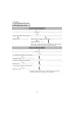
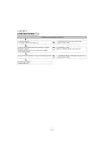
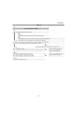
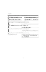
<HDMI input> No video (1)-3
HDMI: No external input video [INPUT-3]
Is INPUT-3 selected on the input select menu screen?
NO
Select INPUT-3 on the input select menu screen for
the right input signal.
YES
Does the HOT PLUG detection function?
NO
Check the line between the pin(18) of SC1503 and
the pin(56) of IC2601.
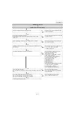
Does the DDC5V signal come from pin (18) of SC1503 to pin (56) of IC2601
(HDMI_SW)?
YES
Does the HPD signal come from pin (55) of IC2601 to pin (19) of SC1503?
NO
Check the line between the pin (55) of IC2601 and
the pin (19) of SC1503.
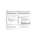
YES
Is IC2601(HDMI-SW) accessed by I2C, with HDMI connected, to read the DDC-I2C
SCL/SDA data?
NO
Check the DDC-I2C line and its peripheral circuits.
SC1501 pin(15)(SCL), pin(16)(SDA)
IC2601 pin(54), pin(53)
YES
Are there the TMDS signal at input pins of IC3301(CPU)?
NO
Check the TMDS line (between SC1503 and
IC2601) and its peripheral circuits.
[IC2601 TMDS input pins]
pin(8/9)(CLK-/+), pin(10/11)(D0-/+), pin(12/13)(D1-/
+), pin(14/15)(D2-/+).
YES
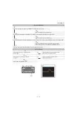
Check the TMDS line (between IC2601 and IC3301)
and its peripheral circuits.
[IC3301 TMDS input pins]
pin(AH35/AH34)(CLK-/+), pin(AG35/AG34)(D0-/+),
pin(AG37/AG36)(D1-/+), pin(AF35/AF34)(D2-/+).
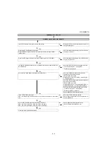
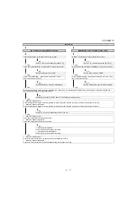
Check the I2C line (between IC2601 and IC3301).
IC2601:pin(71)(SCL), pin(70)(SDA)
IC3301:pin(AN12), pin(AP12)
Check IC2601 and its peripheral circuits.
Is the T-CON PWB connected?
VBO_LOCKN pin(40) of SC3801 become Low if there is no problem in the connec-
tion.
NO
Check the T-CON PWB and harness.
Check IC3301 and SC3801 and their peripheral cir-
cuits in Main PWB.
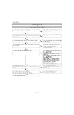
YES
Are the V-By-One HS signal input to the pin of SC3801?
VBO/- (36/37pin), VBO/- (32/33pin),
VBO/- (28/29pin), VBO/- (24/25pin).
NO
Check IC3301 and its peripheral circuits.
(IC3501/IC3502/IC3503/IC3504, etc.)
YES
Check the panel module and harness.
Содержание LC-90LE657U
Страница 6: ...LC 90LE657U 1 1 LC 90LE657U Service Manual CHAPTER 1 SPECIFICATIONS 1 SPECIFICATIONS ...
Страница 7: ...LC 90LE657U 2 1 LC 90LE657U Service Manual CHAPTER 2 OPERATION MANUAL 1 OPERATION MANUAL ...
Страница 8: ...LC 90LE657U 2 2 ...
Страница 9: ...LC 90LE657U 2 3 ...
Страница 10: ...LC 90LE657U 3 1 LC 90LE657U Service Manual CHAPTER 3 DIMENSIONS 1 DIMENSIONS ...
Страница 66: ...LC 90LE657U 7 3 MEMO ...
Страница 68: ...LC 90LE657U 8 2 2 SYSTEM BLOCK DIAGRAM 1 2 3 10 9 7 6 5 4 8 J A B C D E F G H I 13 11 19 18 16 15 14 12 17 ...
Страница 75: ...LC 90LE657U ...
Страница 81: ...LC 90LE657U 1 3 1 2 3 10 9 7 6 5 4 8 J A B C D E F G H I 13 11 19 18 16 15 14 12 17 MAIN Unit Side B ...
Страница 85: ...LC 90LE657U 1 7 1 2 3 10 9 7 6 5 4 8 J A B C D E F G H I 13 11 19 18 16 15 14 12 17 LCD CONTROL Unit Side B ...
Страница 94: ...LC 90LE657U 2 8 1 2 3 10 9 7 6 5 4 8 J A B C D E F G H I 13 11 19 18 16 15 14 12 17 MAIN Unit 7 ...
Страница 100: ...LC 90LE657U 2 14 1 2 3 10 9 7 6 5 4 8 J A B C D E F G H I 13 11 19 18 16 15 14 12 17 LCD CONTROL Unit 2 ...
Страница 101: ...LC 90LE657U 2 15 1 2 3 10 9 7 6 5 4 8 J A B C D E F G H I 13 11 19 18 16 15 14 12 17 LCD CONTROL Unit 3 ...
Страница 102: ...LC 90LE657U 2 16 1 2 3 10 9 7 6 5 4 8 J A B C D E F G H I 13 11 19 18 16 15 14 12 17 LCD CONTROL Unit 4 ...
Страница 103: ...LC 90LE657U 2 17 1 2 3 10 9 7 6 5 4 8 J A B C D E F G H I 13 11 19 18 16 15 14 12 17 LCD CONTROL Unit 5 ...
Страница 104: ...LC 90LE657U 2 18 1 2 3 10 9 7 6 5 4 8 J A B C D E F G H I 13 11 19 18 16 15 14 12 17 LCD CONTROL Unit 6 ...
Страница 105: ...LC 90LE657U 2 19 1 2 3 10 9 7 6 5 4 8 J A B C D E F G H I 13 11 19 18 16 15 14 12 17 LCD CONTROL Unit 7 ...
Страница 106: ...LC 90LE657U 2 20 ...
Страница 129: ...LC 90LE657U ...
Страница 134: ...LC 90LE657U 1 2 MEMO ...


