LC-90LE657U
6 – 1
LC-90LE657U
Service Manual
CHAPTER 6.
TROUBLESHOOTING TABLE
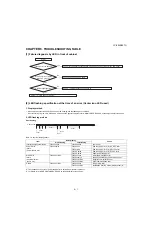
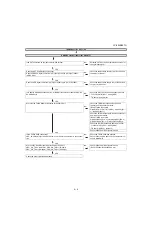
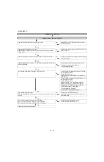
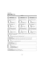
[1] Failure diagnosis by LED in front of cabinet
[2] LED flashing specification at the time of an error (Center icon LED used)
1. Display method
• Since only the center icon LED can be used, slow flashing and fast flashing are combined.
• After recovering from an error, if the same error cannot be generated again, refer to MONITOR ERR CAUSE on the adjustment process mode.
2. LED flashing method
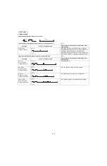
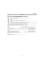
Error flashing
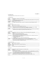
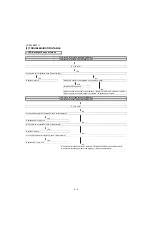
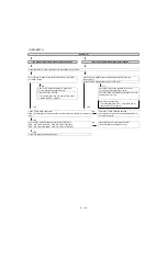
Table 1. Concrete flashing pattern
*2: They depend on the system. Power supply error is defined from product to product.
*3: For details, refer to ERROR STANDBY CAUSE on the adjustment process mode.
Item
Detail display
Cause
Slow flashing
Fast flashing
Inverter/Lamp system failure
Flashes once
Flashes once
Lamp error
Power PWB
failure
(Power failure, etc.)
Flashes twice
Flash once
Power supply error 2 (*2) AC_DET error
Flash twice
Power supply error 2 (*2) UR+13V error
Flash 3 times
Power supply error 2 (*2) D+3.3V error
Flash 5 times
Panel power supply error
Main PWB
failure
(Communication
failure, etc.)
Flashes 3 times
Flashes once
Initial communication error
Flashes twice
Start-up confirmation communication error
Flashes 3 times
Regular communication error
Flashes 5 times
Other communication error
Others
Flashes 4 times
Flashes once
Temperature error
Flashes 3 times
Notification from the main microprocessor (*3)
No
Yes
No
Yes
No
Yes
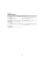
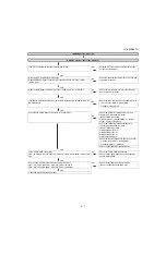
Is the Center Icon flashing?
START
Is the Center Icon lighting
When AC plug on?
Is the Backlight lighting?
Check "[2] LED flashing specification at the time of an error (Center icon LED used)".
Check Power-Unit and AC-cable.
Check "
LED Backlight does not turn on.".
Check "
Picture does not display.".
1600ms
300ms
100ms
400ms
400ms
1600ms
OFF
ON
Center icon
Содержание LC-90LE657U
Страница 6: ...LC 90LE657U 1 1 LC 90LE657U Service Manual CHAPTER 1 SPECIFICATIONS 1 SPECIFICATIONS ...
Страница 7: ...LC 90LE657U 2 1 LC 90LE657U Service Manual CHAPTER 2 OPERATION MANUAL 1 OPERATION MANUAL ...
Страница 8: ...LC 90LE657U 2 2 ...
Страница 9: ...LC 90LE657U 2 3 ...
Страница 10: ...LC 90LE657U 3 1 LC 90LE657U Service Manual CHAPTER 3 DIMENSIONS 1 DIMENSIONS ...
Страница 66: ...LC 90LE657U 7 3 MEMO ...
Страница 68: ...LC 90LE657U 8 2 2 SYSTEM BLOCK DIAGRAM 1 2 3 10 9 7 6 5 4 8 J A B C D E F G H I 13 11 19 18 16 15 14 12 17 ...
Страница 75: ...LC 90LE657U ...
Страница 81: ...LC 90LE657U 1 3 1 2 3 10 9 7 6 5 4 8 J A B C D E F G H I 13 11 19 18 16 15 14 12 17 MAIN Unit Side B ...
Страница 85: ...LC 90LE657U 1 7 1 2 3 10 9 7 6 5 4 8 J A B C D E F G H I 13 11 19 18 16 15 14 12 17 LCD CONTROL Unit Side B ...
Страница 94: ...LC 90LE657U 2 8 1 2 3 10 9 7 6 5 4 8 J A B C D E F G H I 13 11 19 18 16 15 14 12 17 MAIN Unit 7 ...
Страница 100: ...LC 90LE657U 2 14 1 2 3 10 9 7 6 5 4 8 J A B C D E F G H I 13 11 19 18 16 15 14 12 17 LCD CONTROL Unit 2 ...
Страница 101: ...LC 90LE657U 2 15 1 2 3 10 9 7 6 5 4 8 J A B C D E F G H I 13 11 19 18 16 15 14 12 17 LCD CONTROL Unit 3 ...
Страница 102: ...LC 90LE657U 2 16 1 2 3 10 9 7 6 5 4 8 J A B C D E F G H I 13 11 19 18 16 15 14 12 17 LCD CONTROL Unit 4 ...
Страница 103: ...LC 90LE657U 2 17 1 2 3 10 9 7 6 5 4 8 J A B C D E F G H I 13 11 19 18 16 15 14 12 17 LCD CONTROL Unit 5 ...
Страница 104: ...LC 90LE657U 2 18 1 2 3 10 9 7 6 5 4 8 J A B C D E F G H I 13 11 19 18 16 15 14 12 17 LCD CONTROL Unit 6 ...
Страница 105: ...LC 90LE657U 2 19 1 2 3 10 9 7 6 5 4 8 J A B C D E F G H I 13 11 19 18 16 15 14 12 17 LCD CONTROL Unit 7 ...
Страница 106: ...LC 90LE657U 2 20 ...
Страница 129: ...LC 90LE657U ...
Страница 134: ...LC 90LE657U 1 2 MEMO ...

