background image

US

24

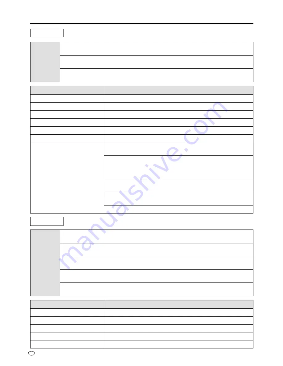
NORMAL

Suitable for viewing a most program material

MOVIE

Suitable for viewing a movie

GAME

Suitable for playing a TV game

Mode

CONTRAST

Adjusting the contrast of the picture

BRIGHT

Adjusting the black level of the picture

RED

Adjusting the red level of the picture

BLUE

Adjusting the blue level of the picture

RESET

Returning to the factory setting

Mode

AV mode

PC mode

Selected item

[CONTRAST]

[TINT]

[COLOR]

[BRIGHT]

[SHARP]

[RESET]

[PRO.]

Setting

Decrease/Increase contrast (0~+60)

Toward purple/Toward green (–30~+30)

Lower/Higher color intensity (–30~+30)

Adjusting the black level (–30~+30)

Adjusting the sharpness (–30~+30)

Returning to the factory setting

“BLACK” Adjusts the degree of dark portions of the picture and
changes the depth. (OFF/HIGH/LOW)

“VDE” Switches on/off the degree of emphasis on the contours of
the picture in the vertical direction. (ON/OFF)
Please use when picture is soft.
*Only for N358 regular video signal

“F-TONE” Changes the degree of emphasis on the skin color. (ON/
OFF)

“C-TEMP” Decrease/Increase color temperature (–5~+5)
*Only for PAL/PAL-60/PAL-M regular video signal

“RESET” Returning to the factory setting

Selected item

[CONTRAST]

[BRIGHT]

[RED]

[BLUE]

[RESET]

Setting

Decrease/Increase contrast (0~+60)

Less/More bright (–30~+30)

Less/More red level (–30~+30)

Less/More blue level (–30~+30)

Returning to the factory setting

Adjustments to the On-Screen Display

Содержание LC-28HM2U Operation

Страница 1: ...and if not installed and used in accordance with the instructions may cause harmful interference to radio communications However there is no guarantee that interference will not occur in a particular installation If this equipment does cause harmful interference to radio or television reception which can be determined by turning the equipment off and on the user is encouraged to try to correct the...

Страница 2: ...y Chart 36 Reference 37 Picture Sizes 37 Troubleshooting 39 Specifications 40 Dimensional Drawings 41 Using the Wall Mount Bracket Option 43 Safety Precautions 2 General Information 4 Supplied Accessories 4 Optional Accessories 4 Names of Parts 5 Example of Application 8 Preparation 9 Connecting the Display and AVC System 9 Batteries for Remote Control 11 System Connection Example 12 Basic Operati...

Страница 3: ...cause the product to fall resulting in serious personal injuries as well as damage to the product Use only a cart stand tripod bracket or table recommended by the manufacturer or sold with the product When mounting the product on a wall be sure to follow the manufacturer s instructions Use only the mounting hardware recommended by the manufacturer 9 When relocating the product placed on a cart it ...

Страница 4: ...inal parts Use of unauthorized parts can result in fire electric shock and or other danger 18 Safety checks Upon completion of service or repair work request the service technician to perform safety checks to ensure that the product is in proper operating condition 19 Wall or ceiling mounting When mounting the product on a wall or ceiling be sure to install the product according to the method reco...

Страница 5: ...3 pins Plug form Cord length 12ft 5 39 64 3 8m for Display 5ft 10 55 64 1 8m for AVC system QACCD5023CEZZ QACCD5024CEZZ OPERATION MANUAL MODE D EMPLOI LC 28HM2 LCD AV MONITOR MONITEUR AV À CRISTAUX LIQUIDES ENGLISH FRANÇAIS Printed in Japan Imprimé au Japon TINS XXXXCEZZ Printed on post consumer recycled paper Imprimé sur du papier recyclé Optional Accessories Bose System Side Speaker Model AN 28S...

Страница 6: ...button p 15 INPUT button p 14 MAIN POWER switch p 14 BRIGHTNESS button p 15 Remote sensor window p 7 OPTIONAL speaker system POWER Standby indicator p 14 Table stand Display input terminal p 9 Speaker cable connection terminals for the optional speaker system AC power input terminal p 9 Back cover p 9 System cable cover p 9 Top view Front view Rear view General Information ...

Страница 7: ...1 S VIDEO VIDEO R AUDIO L VIDEO R AUDIO L AV INPUT 3 AV OUT 1 3 4 7 0 6 9 8 5 2 1 S VIDEO input terminal AV INPUT 2 p 12 2 VIDEO input terminal AV INPUT 2 p 12 3 AUDIO input terminal AV INPUT 2 p 12 4 HEAD PHONE jack p 8 1 AC Power input terminal p 9 2 RS 232C input terminal p 31 3 PC RGB input terminal p 30 4 PC AUDIO input terminal p 30 5 DISPLAY output terminal p 9 6 AUDIO VIDEO input terminal ...

Страница 8: ...uttons Use these buttons to select an AV input terminal directly You can not select an input source to which external equipment is not connected 5 COMPONENT buttons Use these buttons to select a COMPONENT termi nal directly You can not select an input source to which external equipment is not connected 6 PC button Use this button to select the PC mode 7 MUTE button Use this button to temporarily t...

Страница 9: ...E Example of Application Using Headphones You can use any pair of headphones 9 64 3 5mm diameter mini plug to listen to the sound Commercially available 9 64 3 5mm diameter mini jack 16 ohms Indicator Note When connecting headphones the sound from the display speakers is muted indicator appears when a pair of headphones is connected ...

Страница 10: ...lay input terminal on the display and the output terminal on the AVC system until they click 2 Connect the AC power cords to the AC power inputs on the display and the AVC system After connecting the various cables fasten them using the provided cable clamps as shown in the diagram below before mounting the cover Hold this tab and slide the cover downward 2 Removing the system cable cover 3 1 3 2 ...

Страница 11: ...he cover 3 with the two grooves in the upper side of the AVC system and push them gently in Removing the AVC system terminal cover 1 Press both of your thumbs against the arrow marks 2 locations on the upper side of the cover and pull out gently to release the tabs on the upper side 2 Now pull away the entire cover to release the tabs on the lower side Note Before connecting the power cord be sure...

Страница 12: ... batteries can shorten the life of new batteries and or cause old batteries to leak battery fluid Remove batteries as soon as they are exhausted Fluid leaking from the batteries can cause a rash If fluid has leaked out wipe it off with a cloth Remote control handling precautions Do not expose the remote control to excessive shock Do not place the remote control where it can get wet or where the hu...

Страница 13: ...ord 5ft 10 55 64 1 8m AC Power cord Audio Cable 3 AC Power cord To power outlet Component Video cable 3 1 For the best sound quality we recommend you purchase the optional speaker system with built in amplifier The optional speakers are connected to the rear cabinet of the display 2 3 These cables are sold separately To enjoy the beautiful sound with optional Bose System side speakers 1 Make sure ...

Страница 14: ...o Cable Sold separately Sold separately To power outlet Component Video cable Using an external speaker system 1 Connect an audio cable from the audio input terminal LINE IN of the amplifier to the AV INPUT 3 AV OUT terminal on the rear of the AVC system 2 Set the AV 3 setting of the OPTION mode in OUTPUT VARIABLE See page 27 for the setting procedure 3 Press VOLUME on the top of the display or th...

Страница 15: ...right corner of the display CAUTION Never pull the plug of the power cord before you switch off the power by using the MAIN POWER button on the top panel Note Unless external AV equipment is connected the indicator AV 1 appears on the display Switching INPUT Source Press INPUT and select the applicable input source Note The input source mode is skipped if the corresponding input terminal is not co...

Страница 16: ...ume No sound is output under the following conditions By pressing MUTE on the remote control you can temporarily turn the sound off To turn the sound on again press MUTE once more or VOL on the remote control or on top of the display BRIGHTNESS INPUT INPUT VOL Indicator Set to Line output with an external amplifier connected page 13 When headphones are connected page 8 Mark Meaning DARK Indicator ...

Страница 17: ...ray liquid directly on the display When dust has accumulated on the screen use a commercially available cleaning brush anti static brush To protect the screen do not wipe with a dry cloth or a chemically treated cloth Taking care of the cabinet Wipe dirt off using a soft cloth made of flannel for example Never use volatile agents such as benzene or thinner as they will deteriorate the exterior and...

Страница 18: ...TREBLE BASS BALANCE LOUDNESS RESET IMAGE AUTO SYNC AV 3 SIGNAL INFO DISPLAY RESET PC Mode AV Mode Factory Setting Details CONTRAST TINT COLOR BRIGHT Black level SHARP SHARPness BLACK Black stretching sense of depth VDE Vertical Detail Enhancement Only for N358 F TONE Flesh Tone C TEMP Color TEMPerature Only for PAL PAL 60 PAL M TREBLE BASS BALANCE LOUDNESS PRO PICTURE SOUND NORMAL 60 0 0 0 0 OFF O...

Страница 19: ...ges 1 Press MENU to display the Menu screen Press to move the cursor to VIEW and then press ENTER 2 Press to move the cursor and select the desired mode Then press ENTER Adjusting the Position of the Picture Continue the following procedure if you want to adjust the position vertically horizontally 3 Press to move the cursor and select the desired adjustment Then press ENTER 4 Press to make the ad...

Страница 20: ...t width ratio is 4 3 The screen shows a movie size display for software driven movies Compressed to the 4 3 format a video image is shown full size PC mode Mode FULL DOT BY DOT Widened picture to full screen size Picking out the display mode of the input signal of the connected computer this function displays the picture in the center without enlargement This unit is compatible with the following ...

Страница 21: ...ifting the picture horizontally 30 30 Returning to the factory setting ON OFF V Shifting the picture vertically 15 15 H Shifting the picture horizontally 30 30 RESET Returning to the factory setting PC mode Mode SIDE BAR CINEMA FULL DOT BY DOT Selected item CLOCK PHASE V POSI H POSI RESET Setting Adjust when flicker in the form of vertical stripes appears 90 90 Adjust if contrast can not be obtain...

Страница 22: ...icture When watching a 4 3 format SIDE BAR picture adjusted to a full size using the VIEW mode the peripheral picture may be invisible or partly deformed In order to watch the original picture as intended by the copyright holder please watch using the SIDE BAR mode Depending on the signal received or the movie software correct operation cannot be obtained with the AUTO setting In this case after s...

Страница 23: ...e the cursor to BRIGHT and then press ENTER 2 Press to make the adjustment Then press ENTER Adjustments to the On Screen Display BRIGHT Maximum brightness NORMAL Brightness 60 Suitable for viewing in well lit areas Saves energy DARK Brightness 20 Sufficiently bright when viewing in dim areas Mode POWER 1 2 3 1 2 PC INPUT COMPONENT MUTE MENU ENTER VOL AV INPUT LCD MONITOR ...

Страница 24: ...t an appropriate position for contents of the picture or lighting of the place Details of modes and adjustment items are described on the following pages 1 Press MENU to display the Menu screen Press to move the cursor to PICTURE and then press ENTER 2 Press to move the cursor and select the desired mode Then press ENTER For Fine Picture Adjustment Continue the following procedure if you want to a...

Страница 25: ...vel 30 30 Adjusting the sharpness 30 30 Returning to the factory setting BLACK Adjusts the degree of dark portions of the picture and changes the depth OFF HIGH LOW VDE Switches on off the degree of emphasis on the contours of the picture in the vertical direction ON OFF Please use when picture is soft Only for N358 regular video signal F TONE Changes the degree of emphasis on the skin color ON OF...

Страница 26: ...ribed on the following pages 1 Press MENU to display the Menu screen Press to move the cursor to SOUND and then press ENTER 2 Press to move the cursor and select the desired mode Then press ENTER For Fine Sound Adjustment Continue the following procedure if you want to adjust the sound item by item 3 Press to move the cursor and select the desired adjustment Then press ENTER 4 Press to make the ad...

Страница 27: ...L30 is from the most left and R30 is from the most right LOUDNESS Modulation of the sound ON OFF RESET Returning to the factory setting Mode PC mode Selected item TREBLE BASS BALANCE LOUDNESS RESET Setting Decrease Increase treble level 30 30 Decrease Increase bass level 30 30 Adjusts the balance of right and left sound L30 is from the most left and R30 is from the most right Modulation of the sou...

Страница 28: ...tails of adjustment items are described on the following pages 1 Press MENU to display the Menu screen Press to move the cursor to OPTION and then press ENTER 2 Press to move the cursor and select the desired mode Then press ENTER 3 Press to move the cursor and select the desired adjustment Then press ENTER 4 Press to make the adjustment and then press ENTER POWER 1 2 3 1 2 PC INPUT COMPONENT MUTE...

Страница 29: ... from side speakers AUTO N358 N443 PAL PAL 60 PAL M SECAM The settings are stored per connection terminal AV 1 2 3 Even if the power to the unit is cut off the settings will remain in the memory Turns ON or OFF the channel indicators which are displayed when changing channels Returning to the factory setting PC mode Mode AUTO SYNC SIGNAL INFO Selected item Using this function a stable computer scr...

Страница 30: ...T 1 Set the AV 3 setting in the OPTION mode to INPUT For the opera tion refer to Adjusting the OPTION Settings page 27 2 Select AV 3 for the input source by using either the INPUT button or the AV INPUT buttons AV 1 AV 2 AV 3 COMPONENT1 COMPONENT2 PC Changing INPUT to OUTPUT Select the input source other than AV 3 before going to the OPTION mode to perform Step 1 1 Set the AV 3 setting in the OPTI...

Страница 31: ... and compatible computers Display mode Horizontal dots Vertical lines 640 480 800 600 1024 768 Vertical frequency 60 85 Hz Clock frequency Approx 30 MHz Approx 50 MHz Approx 80 MHz Note VGA SVGA XGA Connecting to a Computer 5 15 10 1 11 6 1 Video input red 2 Video input green sync on green 3 Video input blue 4 Reserve input 1 5 Composite sync 6 Earth red 7 Earth green sync on green 8 Earth blue 9 ...
Страница 32: ...ettings on the computer to match the display s communications conditions The display s communications settings are as follows Communication procedure Send the control commands from the computer via the RS 232C connector The display operates according to the received command and sends a response message to the compu ter Do not send multiple commands at the same time Wait until the computer receives...

Страница 33: ...2 video input 3 component input Inputs confirmation Displays the input source as a CH call 0 Display CH call off 1 Display CH call on Inputs RGB PC Inputs VIDEO 1 3 1 Input COMPONENT1 2 Input COMPONENT2 1 AUTO 2 PAL 3 SECAM 4 NTSC 443 5 NTSC 358 6 PAL M 7 reserve 8 PAL 60 CONTRAST 0 60 BRIGHT 30 30 COLOR 30 30 TINT 30 30 SHARP 30 30 0 Displays the setting value on OSD except PRO settings 1 Resets ...
Страница 34: ...e setting value except PRO Settings BLACK 0 OFF 1 LOW 2 HIGH VDE 0 OFF 1 ON F TONE 0 OFF 1 ON C TEMP 5 5 Only for PAL PAL 60 PAL M CONTRAST 0 60 BRIGHT 30 30 RED 30 30 BLUE 30 30 0 Displays the setting value on OSD 1 Resets the setting value Controls the current volume Controls the volume of AV speakers headphones Controls AV line volume Controls the volume of PC speakers headphones Controls PC li...

Страница 35: ...RW RW RW RW W BALANCE 30 30 BASS 30 30 TREBLE 30 30 0 LOUDNESS OFF 1 LOUDNESS ON 0 Displays the setting value on OSD 1 Resets the setting value In the AV mode the CLOCK cannot be adjusted In the AV mode the PHASE cannot be adjusted H POSI V POSI 0 Displays the setting value on OSD 1 Resets the setting value CLOCK reserve PHASE reserve H POSI V POSI 0 Displays the setting value on OSD 1 Resets the ...

Страница 36: ...VLMP RLMP IMPI IMAU IMV3 IMAW RW RW RW RW W RW RW RW RW RW RW RW RW RW RW RW RW RW CLOCK PHASE H POSI V POSI 0 Displays the setting value on OSD 1 Resets the setting value 1 SIDE BAR 2 FULL 3 DOT BY DOT 4 DOT BY DOT WIDE reserve 5 CINEMA 1 SIDE BAR 2 WIDE STRETCH 3 reserve 4 reserve 5 CINEMA 1 reserve 2 STRETCH 3 FULL Presence absence of CH call when selecting input source using command 0 OFF 1 ON...

Страница 37: ...ded display signals and personal computer signals are as follows Connecting to a Computer Horizontal Frequency kHz Vertical Frequency Hz VESA Standard Resolution 720 400 VGA 640 480 SVGA 800 600 XGA 1 024 768 27 0 31 5 37 9 31 5 34 7 37 9 37 5 43 5 37 9 44 5 48 1 46 9 53 7 56 5 58 1 60 70 85 60 70 72 75 85 60 70 72 75 85 70 72 ...

Страница 38: ... s with squeeze recording For high grade pictures such as HDTV Wide size Subtitles 9 00 Side Bars appear on the left and right Screen with black bands at the top and bottom and left and right of the display Screen with black bands at the left and right of the display Picture appears stretched vertically Subtitles 9 00 Picture is perfectly round with projections enlarged at the top and bottom Full ...
Страница 39: ...or high grade pictures such as HDTV Wide size Picture is stretched horizontally while black bands appear to make the vertical horizontal ratio 16 9 Full picture is visible but black bands appear at the top and bottom Maximum stretching in the horizontal direction Full picture is visible Picture becomes perfectly round Black bands appear at the top and bottom 9 00 Subtitles Picture is stretched ove...

Страница 40: ...he optional side speakers VARIABLE for a commercially available speaker system Make sure COLOR and TINT settings Make sure CONTRAST and BLACK level settings are not set too high Check that RED and BLUE settings are near the center Make sure BRIGHTNESS setting is not set too low Check to see if BRIGHTNESS mode is not set to DARK Change to MEDIUM or BRIGHT Lamp may have malfunction Contact your near...

Страница 41: ...32C control Headphones jack 9 64 3 5 mm diameter mini jack 16 ohms Power Inlet for AC power cord FUNCTIONS OSD Language English Reverse Invert Mirror image only Brightness NORMAL BRIGHT DARK Component capability 480i 480p 1080i 720p PC capability VGA SVGA XGA WIDE view mode STRETCH FULL AUTO wide view NTSC picture only Automatically changing to CINEMA mode POWER SUPPLY AC auto power voltage capabi...

Страница 42: ...41 US Dimensional Drawings Display Reference POWER 17 41 64 448 mm 27 13 64 690 8 mm 20 7 16 519 mm 19 3 32 485 mm 10 29 32 277 mm 2 11 32 59 7 mm 10 29 32 277 mm 7 8 22 2 mm 4 7 16 112 8 mm ...

Страница 43: ...US 42 Reference AVC System AVC SYSTEM POWER 14 11 64 360 mm 2 1 4 57 mm 2 9 16 65 mm S VIDEO VIDEO L AUDIO R HEAD PHONE AV INPUT 2 3 47 64 95 mm 10 5 8 270 mm 10 5 8 270 mm ...

Страница 44: ...unted should be made of plywood or real wood of 5 8 15 mm or over in thickness otherwise the wall would be necessary a reinforcement work for the safety The screws to fix the base bracket on the wall are not included in the product and in the optional bracket Use the commercially available screws however make sure the dimensions shown as follows 7 to 11 pieces Reference 23 64 33 64 9 mm 13 mm 5 32...

Страница 45: ...tend the duration of any warranties beyond the time period described herein on behalf of Sharp The warranties described herein shall be the sole and exclusive warranties granted by Sharp and shall be the sole and exclusive remedy available to the purchaser Correction of defects in the manner and for the period of time described herein shall constitute complete fulfillment of all liabilities and re...

Отзывы: