5 – 2
AY-XPC15PU
2
L2
L1
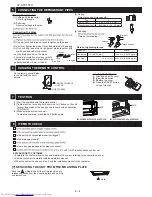
Connecting Cable
Earth Wire
Terminal Board
5
Short screw
8
Cable cover
Cable Clump
Cable Holder
Connection Holder
(For Wire Conduit)
Fig.1
(AY-XPC15PU, AY-XPC18PU,
AY-XP24PU)
Installing the mounting plate
The mounting plate should be installed on a wall which can support the weight
of the indoor unit.
(1)
the piping hole.
y.
(2) Secure the mounting plate to the wall with the long screws and
ffness.
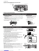
1 PLACING THE MOUNTING PLATE AND MAKING A PIPING HOLE
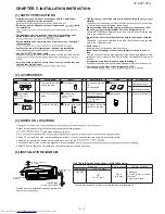
[5].INSTALLATION DIMENSION OF INDOOR UNIT
[6].INSTALLATION PROCEDURE
Length unit: in (mm)
Wall
Indoor
Outdoor
Cut with a saw.
Cap
0.2 in (5 mm)
Sleeve
(Downward to
outdoor)
1
!#$$&'@ATE
2
@!$&\^_`
Making a piping hole
(1) Drill a piping hole with concrete drill or
a hole saw with a 0.2inch (5mm) down
ward slant to the outside.
the diameter is 2.8inch (70mm).
(2) Set the sleeve and caps.
A
J
I
F
E
H
I
E
&
F
D
D
J
E
B
A
C
2.8 (70)
Outline of indoor unit
Connecting wires and the ground wire
Use solid conductor A&{| A&{|}~{| A&
if required by local electrical code)
Use double insulated copper wire with 600 V insulation.
Use copper conductors only.
Follow local electrical codes.
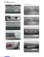
(1) Process the end of the connecting cable for the indoor side.
(2) Tf^}
(3) Tff the Connection Holder from the Wire Conduit and attach the Con-
^@$}~ }
~| ^r.
(5) Attach the Cable Holder and Connection Holder to Cabinet with screw}_
to “
ATTACH THE CABLE HOLDER AND CONNECTION HOLDER
”. (Fig.3
and Fig.4)
(6) }
(7) Open the Open Panel.
(8) Connect the Connecting Cable to Terminal Board. (Fig.1)
(9) Fix the Cacle cover with the screw.
(10) Tighten the Connection Holder to Wire Conduit.
(11) Close the Open Panel.
Cautions:
Be sure to put the cable leads deep into the terminal board and tighten up the
Be very careful not to confuse the terminal connections. Wrong cabling may
damage the internal control circuit.
’s termi-
nal board and those of the outdoor unit.
} After tightening, pull the wire conduit
0.3 in (8 mm)
(8 mm) 0.3 in
2 inch (50 mm)
2.4 inch (60 mm)
2 CONNECTING THE CABLE TO THE INDOOR UNIT
Earth Wire
Center of wall hole
5.4 (137)
5.4 (137)
3.2 (80)
3.2 (80)
#~^}~
1.3 (33)
1.7 (42)
50 (2)
12.8 (325)
Top of connecting
pipes
2
L2
L1
2
L1
L2
L1
L2
Power supply
208/230 V AC,
1phase 2 wires.
!#!!_#$
Disconnect
switch
Terminal board 2
&
T
erminal board 1
$!!_#$
Содержание AY-XP24PU
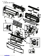
Страница 33: ...AY XPC15PU 2 1 INDOOR UNIT PARTS ...

