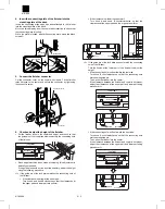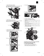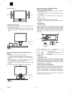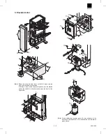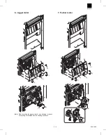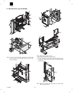
4. Insert the connecting plate of the finisher into the
mounting plate of the desk.
Insert the connecting plate which has been attached to the finisher
into the mounting plate of the desk.
Move the finisher away from the copier after insertion to check that
the connecting plate is locked.
While the plate is locked, attach the securing plate using two black
screws C.
5. Connect the finisher connector.
Cut the connector cover on the copier with nippers. Fit the finisher
relay harness to the copier and secure the connector by tightening
the connector screw.
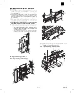
6. Check and adjust the height of the finisher.
•
Put the finisher close to the copier and adjust and check so that
the guide pin of the lock plate enters smoothly the connecting hole
of the finisher.
•
Since adjustment has been made at shipping, this adjustment is
basically not needed.
If the guide pin should not be inserted smoothly, adjust the height
using the following procedure.
<1> If the guide pin of the lock plate matches the connecting hole of
the finisher:
•
If the clearance is narrow at the upper part:
Turn knob A and knob B clockwise so that the clearances at
the upper part and lower part are uniform.
•
If the clearance is wide at the upper part:
Turn knob A and knob B counterclockwise so that the
clearances at the upper part and lower part are uniform.
<2> If the guide pin of the lock plate does not match the connecting
hole of the finisher:
Turn the knobs at the lower part of the finisher to adjust the
height.
•
If the connecting hole is offset toward the rear side:
Turn knob B counterclockwise so that the connecting hole
matches the guide pin.
Then, push the finisher into the copier.
If the clearance between the finisher and copier is not proper,
adjust the clearances at the upper part and lower part using
procedure <1>.
•
If the connecting hole is offset toward the front side:
Turn knob A counterclockwise so that the connecting hole
matches the guide pin.
Then, push the finisher into the copier.
If the clearance between the finisher and copier is not proper,
adjust the clearances at the upper part and lower part using
procedure <1>.
Connecting
plate
Mounting plate
Securing plate
Screws C
Connector cover
Screw
Connector
Lock plate
Guide pin
(Top view)
Knob B
Knob A
Clearance
Clearance
Guide pin
(Top view)
Knob A
Knob B
Guide pin
(Top view)
Knob A
Knob B
AR-FN3
8/19/1999
2 – 2
Содержание AR-FN3
Страница 20: ...15 15 15 15 16 AR FN3 8 19 1999 5 7 ...
Страница 27: ... Rollers Paper guides AR FN3 7 2 8 19 1999 ...
Страница 28: ...AR FN3 8 19 1999 7 3 ...
Страница 29: ... Gears Others Sensors Belts AR FN3 7 4 8 19 1999 ...
Страница 51: ...3 Main PWB page arrangement 1 2 AR FN3 10 9 8 6 1999 ...
Страница 52: ...Main PWB page arrangement 2 2 AR FN3 8 6 1999 10 10 ...

