2008-03-14
LC-42SB45U
35
No sound from external input devices (2)
↓
Does not the sound of the audio signal input to INPUT 3(Composite, Y/C) go out?
MAIN UNIT:
↓
↓
YES
↓
YES
No sound from external input devices (3)
↓
Does not the sound of the audio signal input to INPUT 7 (VGA) go out?
MAIN UNIT:
↓
↓
YES
↓
YES
No sound from external input devices (4)
↓
Does not the sound of the audio signal input to INPUT 4/5/6 (HDMI1/2/3) go out?
↓
↓
YES
The digital audio signal is not output (1)
↓
No digital audio signal output from SPDIF_OUTPUT terminal.
TEREMINAL UNIT:
↓
↓
NO
Is the audio signal properly sent to pin (4) (AV3_AudioLIN) and pin
(6) (AV3_AudioRIN) of CN650?
NO
Check the connection to CN650 and the external input device.
Refer to
“
No sound output in all modes
”
.
Is the audio signal properly sent to pin (K23) (AV3_LIN) and pin
(K24) (AV3_RIN) of IC U400?
NO
Check the line between CN650 and IC U400.
Is the audio signal properly sent to pin (2) (VGA_AudioLIN) and pin
(3) (VGA_AudioRIN) of CN555?
NO
Check the connection to CN555 and the external input device.
Refer to
“
No sound output in all modes
”
.
Is the audio signal properly sent to pin (K25) (VGA_LIN) and pin
(K26) (VGA_RIN) of IC U400?
NO
Check the line between CN555 and IC U400.
Refer to
“
No sound output in all modes
”
.
Is picture of the signal input from INPUT 4/5/6 displayed?
NO
Refer to
“
Does not the picture of the HDMI signal input to
HDMI1/2/3 go out?
”
.
Check IC U400 and its peripheral circuits.
Is ASPDIF audio signal output from pin (B22) of IC U400 to pin (6)
of connector CN553?
YES
Check the connection to SPDIF_OUT and external devices.
Содержание AQUOS LC-42SB45U
Страница 6: ...LC 42SB45U 6 TV Front view TV Rear view ...
Страница 11: ...2008 03 14 LC 42SB45U 11 3 DIMENSIONS ...
Страница 50: ...LC 42SB45U 50 3 2 U102 LP2996MRX PSOP 8 3 2 1 Pin Connections and short description ...
Страница 54: ...LC 42SB45U 54 3 8 U402 MX25L3205DMI 12G SOP 16 3 8 1 Block Diagram ...
Страница 55: ...2008 03 14 LC 42SB45U 55 3 8 2 PIN CONFIGURATION ...
Страница 56: ...LC 42SB45U 56 CHAPTER 6 BLOCK DIAGRAM WIRING DIAGRAM 1 MT5382 POWER MAGAGEMENT BLOCK DIAGRAM ...
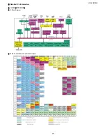
Страница 57: ...2008 03 14 LC 42SB45U 57 2 MAIN BOARD BLOCK DIAGRAM ...
Страница 58: ...LC 42SB45U 58 3 WIRING DIAGRAM ...
Страница 59: ...LC 42SB45U CHAPTER 7 PRINTED WIRING BOARD 1 MAIN UNIT PRINTED WIRING BOARD MAIN Unit Side A 59 ...
Страница 60: ...60 LC 42SB45U MAIN Unit Side B ...
Страница 61: ...LC 42SB45U 1 POWER UNIT PRINTED WIRING BOARD POWER Unit Side A 61 ...
Страница 62: ...LC 42SB45U POWER Unit Side B 62 ...
Страница 63: ...LC 42SB45U 63 3 KEY BOARD UNIT PRINTED WIRING BOARD KEY BOARD Unit Side A KEY BOARD Unit Side A ...
Страница 64: ...64 LC 42SB45U IR Unit Side A 3 IR UNIT PRINTED WIRING BOARD IR Unit Side A Cn001 A2 ...
Страница 107: ...2008 03 14 LC 42SB45U 107 2 CABINET PARTS ...


