background image

D-4

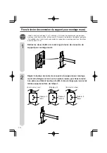
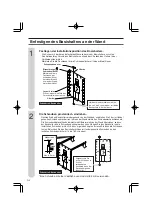
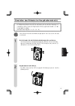
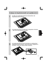
Vergewissern Sie
sich mit Hilfe des in
Schritt 1
verwendeten
Senkbleis, dass der
Basishalter genau
lotrecht ist.

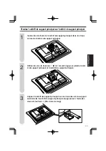
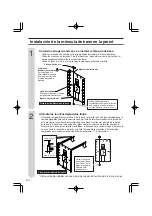
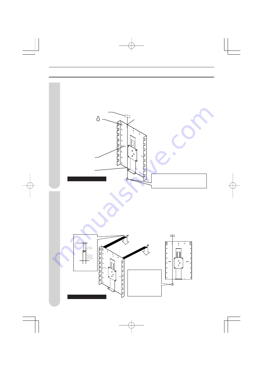
Befestigen des Basishalters an der Wand

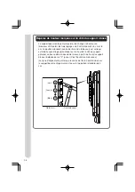
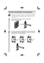
Festlegen der Installationsposition des Basishalters.

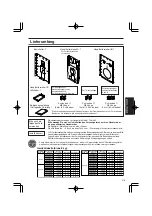
Die Schnur mit der daran befestigten Münze lotrecht zum Basishalter ausrichten.
Den horizontalen Versatz des Basishalters anhand der V-Kerben des Halters in der
Vertikalposition prüfen.
Markieren Sie die Positionen für die Schraubenlöcher mit einem Bleistift usw.

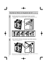
Die Schrauben provisorisch eindrehen.

Nehmen Sie den Basishalter vorübergehend von der Wand ab, und drehen Sie 2 der im Handel
gekauften Schrauben provisorisch in die an der Wand markierten Schraubenlochpositionen ein.
Die Schraubenköpfe sollten dabei mehrere Millimeter weit von der Wand überstehen, so dass
der Basishalter an die Schrauben gehängt werden kann. Hängen Sie den Basishalter an die
installierten Schrauben, prüfen Sie, dass er gerade hängt, und ziehen Sie dann die Schrauben
fest an. Befestigen Sie den Basishalter mit den im Handel gekauften Schrauben an den
restlichen Schraubenlöchern (14 bis 18 Schrauben).

*Eine Schraube mit einer Kopfhöhe von maximal 8,5 mm verwenden.

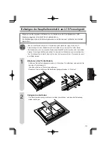
Zellophanband usw.

Birnenförmige
Schraubenlöcher

Markieren Sie die
Positionen der
Schraubenlöcher
mit einem Bleistift
usw. an der Wand
hinter dem Halter.

Horizontal und vertikal ausrichten,
bis sich die Schnur mit der vertikalen
Bezugslinie (V-Kerbe) deckt.

V-Kerbe

Layout-Linie

Diese Linie auf die Mitte des
Fernsehschirms ausrichten.

V-Kerbe

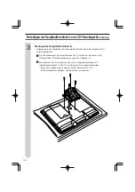
1

2

Zubehörteil: Basishalter

Zubehörteil: Basishalter

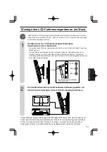
Max. 8,5 mm

Mindestens

4 mm

Wand

Содержание AN-52AG1

Страница 1: ...bfernsehgerät Ménsula de montaje el TV color de cristal líquido en la pared 取扱説明書 OPERATION MANUAL MODE D EMPLOI BEDIENUNGSANLEITUNG MANUAL DE MANEJO ご注意 本製品 SHARP AN 52AG1 は 下記の SHARP 製液晶テレビ専用のものです これ以外の製品とともに使用すると 事故を引き起こすおそれがあります CAUTION This product SHARP AN 52AG1 is only to be used for the SHARP LCD TV as follows Using the bracket for another product could cause an accident ...

Страница 2: ...2 目次 安全に正しくお使いいただくために 3 外形寸法図 4 同梱品 5 壁用金具を壁に取り付ける 6 本体金具ユニットAの角度を設定する 9 本体金具ユニットAを液晶テレビに取り付ける 11 本体金具ユニットBを本体金具ユニットAに取り付ける 13 壁用金具結合レバーを設定する 14 液晶カラーテレビを壁に取り付ける 15 お客様ご相談窓口のご案内 16 ...

Страница 3: ...は この説明書に従って施工してください 落下に よるケガや破損の原因となります 取り付け工事は 確実な作業が必要ですので 販売店や工事店にご相談ください 取り付けの際には 金具等に指などをはさまないようにご注意ください 取り付ける壁面は十分な強度があることを確認してください 壁に補強材の入っ ている部分に取り付けてください 取り付け金具には他の荷重をかけないでください 落下によるケガや破損の原因 となります 取り付け部品の改造 変更は行わないでください 落下によるケガや破損の原因 となります 安全のため特に注意してください 警告 注意 湿気やほこりの少ない場所へ 液晶カラーテレビのキャビネットの 通風孔をふさがないでください 通 風孔をふさぐと内部に熱がこもり 火災の原因となることがあります 次のような使い方はしないでください 押し入れ 本箱など風通しの悪い狭 い所に設置する 設置した液晶...

Страница 4: ...守りください 液晶カラーテレビの設置には特別な技術 が必要ですので 必ず専門の取り付け工 事業者へご依頼ください お客様による 工事は一切行わないでください 取り付 け不備 取り扱い不備による事故 損傷に ついては 当社は責任を負いません 35 35 70 70 299 6 265 9 55 55 55 55 430 55 55 55 17 φ6 5 265 294 9 10 55 55 55 55 410 55 55 55 15 19 160 215 310 40 4 φ4 5 4 φ15 4 φ12 256 422 4 44 1 70 70 97 97 テ レ ビ に 本 体 金 具 ユ ニ ッ ト A を 取 り 付 け る 際 に は こ の 取 付 孔 を 使 用 し ま す こ の 孔 の 裏 側 に A の 刻 印 が あ り ま す ...

Страница 5: ...くご覧になる姿勢や目 線 視聴範囲に合わせて設置位置を決めてください 取り付け強度の不十分 または取り付け不備が原因で液晶カラーテレビが落下する等に対す る責任は 当社では一切負いかねますのでご了承ください ねじの M5 はねじ部の径が 5mm であることを表します 使用しないねじも保管してください 本体金具ユニッ トA 1 個 取扱説明書 本書 垂直設置用に組み立て済み ねじ A M5 長さ 8mm 4 本 ねじ C M4 長さ 6mm 6 本 設置位置について ご用意ください ねじ B M6 長さ 12mm 4 本 本体金具ユニッ トB 1 個 本体金具ユニッ ト B 用 補助金具 1 個 壁掛け金具固定用及び本体金具 ユニット B 補助金具固定用 本体金具ユニット A B 固定用 テレビ取付用 日本語 同梱品 壁用金具 1 個 ...

Страница 6: ...マーク位置に市販のねじ 2本 を仮止 めします このとき ねじ頭は 壁用金具が掛けられるよう壁から4ミリ以上浮いた状態 にします 取り付けたねじに壁用金具を掛け 左右に傾いていないか確認後 しっかりと ねじを締めます 残りのねじ孔にも市販のねじ 14 18本 を使って止めます 2 手順1で使用した おもりをつけた糸 を使って 垂直の 確認をします 8 5mm以下 4mm以上 壁 壁 同梱品 壁用金具 ねじ頭の高さは8 5ミリ以下のものをご使用ください セロハンテープなど ケガキ線 テレビ画面のセンターを あらわしています V字みぞ 形状のねじ孔 ねじ孔に合わせて エンピツなどで背面の 壁に印をつけます V字みぞ 垂直基準線 V字みぞ と糸が重なる ようにして水平 垂直を合わせます 同梱品 壁用金具 ...

Страница 7: ...にテープなどを貼り テレビの外形寸法の目印をつける 24ケ所の目印から対角線を引き その交点 テレビ画面の中心となる位置 に目印をつける 3この目印と壁用金具のディスプレイ中心を示す刻印を合わせ 壁用金具を 壁に取り付ける 4壁掛け金具ユニットを液晶テレビに取り付けた後 壁面の寸法の目印 テレビの四隅 を目安にして テレビを壁用金具に取り付ける 5目印のテープ類を取り除く 例 LC 52GX2 サイドスピーカータイプ を壁掛け設置する場合 壁の目印 1482 52GX2 1264 52GX1 761 300 151 430 単位 mm テープ 寸法の目印 180 日本語 ...

Страница 8: ...本壁掛け金具は 0cm 標準 5cm 5cmと 液晶テレビの高さを 3段階に変えることができます 本体金具ユニットの最上部のピンが壁用金具の上から2番目の溝 黄色で 0 の表示 にかかった状態が標準 テレビ画面センター です 下図参照 壁用金具のテレビ画面センターをあらわすケガキ線も 0cm 標準 状態で のものです 壁用金具側面の高さ表記について 5 5 0 0 5 5 緑 壁側 TVセット側 黄 青 ...

Страница 9: ...4本 を外します この4本のねじのうち2本は角度を設定する とき 手順4 に使用します ねじはなくさないように大切に保管ください 壁掛け金具ユニッ トは 梱包状態では垂直設置用 0 に組み立てられており 斜め設 置の場合は以下の手順で設置角度の設定が必要です 0 5 10 15 20 の5つの角度に設定可能です 壁掛け金具ユニットの角度調整の際 指などをはさまないようにご注意ください 1 2 本体金具ユニットAを開く 液晶テレビセット側の金具を図に従い 矢印方向に引きます 日本語 ...

Страница 10: ...15 5 10 10 20 5 0 15 3 1 0 5 5 0 5 1 5 0 2 0 0 5 10 15 20 1 0 5 0 1 5 10 20 0 2 0 0 10 10 1 0 10 20 5 0 15 10 20 5 0 15 10 20 5 0 15 15 1 5 10 20 5 0 15 20 5 0 15 20 20 0 15 5 10 10 20 5 0 15 手順 1 で外した 4 本のねじのうち 2 本を使い ねじを締める 例 15 に設定する場合 梱包状態の垂直 0 に戻すときのみ 手順1で外した4本のねじを全て使います ...

Страница 11: ...液晶カラーテレビの背面を上 側にして やわらかい布やクッションなどの上に置いて行ってください 52型は立てた状態でもスタンドを外すことができますが 壁掛け金具が取り付けやすい寝か せた状態での取り外し方を説明しています テレビを起こすときは スピーカー部分を持たないようにしてください 故障の原因となる ことがあります 1 テーブルスタンドを外す テーブルスタン ドを止めているねじ 4本 を外し テーブルスタン ドを外します 矢印方向に引いてから外します 取り外したスタン ド固定ねじ 4本 は保管してください ケーブルの処理をする 端子カバーを外し ケーブルの配線をしたうえで再びカバーを取り付けます 2 日本語 ...

Страница 12: ...液晶テレビに取り付ける つづき 本体金具ユニットAを取り付ける 角度設定した壁掛け金具ユニッ トを液晶カラーテレビの背面に取り付けます z 液晶カラーテレビ背面の孔 4ヶ所 に本体金具ユニットAのねじ孔 4ヶ所 を合 わせます 刻印A x 同梱のテレビ取付用ねじB M6 長さ12mm 4本を使用してしっかりと締め 付けます 液晶カラーテレビ背面の孔 4ヶ所 にキャップが付いている場合は あらかじ め取り外しておいてください 3 ...

Страница 13: ...13 本体金具ユニットAの角孔に本体金具ユニットBのフック部を差し込む 本体金具ユニットBを本体金具ユニットAに取り付ける 付属のねじ C M4 長さ 6mm 6 本で本体金具ユニットAと本体金具 ユニット B を固定する 1 2 本体金具ユニット B に本体金具ユニットB補助金具のねじ孔をあわせ 付属のねじ A M5 長さ 8mm 2 本で固定する 3 日本語 ...

Страница 14: ...ねじ M4 長さ 6mm を 2 本外す 1 2 壁用金具結合レバーの高さを調整し 設定したい高さにレバーを合わせ 手順1で外したねじ M4 長さ 6mm を 2 本止める 下記手順 1 と 2 は必ず行ってください 壁用金具結合レバーを固定しなければ 液晶カラー テレビが落下してケガの原因となります 壁用金具結合レバーのねじは 出荷時は 5cm に設定されています 上 5cm 0 設定 下 5cm 5 表示 緑色 0 表示 黄色 5 表示 青色 5 0 5 ...

Страница 15: ... ー ージ ジ ジ ジ ジで で で で で高 高 高 高 高さ さ さ さ さを を を を を設 設 設 設 設定 定 定 定 定し し し し した た た た た壁 壁 壁 壁 壁用 用 用 用 用金 金 金 金 金具 具 具 具 具 結 結 結 結 結合 合 合 合 合レ レ レ レ レバ バ バ バ バー ー ー ー ーの の の の の表 表 表 表 表示 示 示 示 示 色 色 色 色 色 表 表 表 表 表示 示 示 示 示 と と と と と一 一 一 一 一致 致 致 致 致す す す す する る る る ると と と と とこ こ こ こ ころ ろ ろ ろ ろに に に に には は は は はめ め め め め込 込 込 込 込ん ん ん ん んで で で で でく く く く くだ だ だ だ ださ さ さ さ さい い い い い 2 現在の角度設定状態より...

Страница 16: ...休日を除く 担当地域 拠 点 名 電 話 番 号 郵便番号 所 在 地 札幌サービスセンター 011 641 4685 063 0801 札幌市西区二十四軒1条7丁目3 17 仙台サービスセンター 022 288 9142 984 0002 仙台市若林区卸町東3 1 27 さいたまサービスセンター 048 666 7987 331 0812 さいたま市北区宮原町2 107 2 宇都宮サービスセンター 028 637 1179 320 0833 宇都宮市不動前4 2 41 東京テクニカルセンター 03 5692 7765 114 0013 北区東田端2 13 17 多摩サービスセンター 042 586 6059 191 0003 日野市日野台5 5 4 千葉サービスセンター 047 368 4766 270 2231 松戸市稔台295 1 横浜テクニカルセンター 045 753 4647 2...

Страница 17: ...60 0065 高松市朝日町6 2 8 福岡サービスセンター 092 572 4652 816 0081 福岡市博多区井相田2 12 1 那覇サービスセンター 098 861 0866 900 0002 那覇市曙2 10 1 中 国 地 区 四 国 地 区 九 州 地 区 沖縄 奄美地区 地区別窓口一覧 つづき 受付時間 月曜 土曜 午前9時 午後6時 日曜 祝日 午前10時 午後5時 年末年始を除く FAX送信される場合は お客様へのスムーズな対応のため 形名やお問い合わせ内容のご記入をお願いい たします 所在地 電話番号などについては変更になることがありますので その節はご容赦願います 06 08 日本語 ...

Страница 18: ...e TV E 3 Installing the based bracket to the wall E 4 Adjusting the Angle of Main bracket unit A E 7 Mount main bracket unit A to the LCD television E 9 Mount main bracket unit B to the main bracket unit A E 11 Set the wall mount bracket connection lever E 12 Installing the LCD color TV on the wall E 13 ...

Страница 19: ...ious injury Caution Not following these instructions could result in injury or property damage Follow the instructions in this manual regarding the installation method and installation orientation Not following these instructions could results in injury or damage from falling parts Accurate work is required for the installation work so please have it done by the dealer or qualified contractor Duri...

Страница 20: ...gn so that the strength of the installation location is sufficiently strong to support the weight of the LCD color TV and the wall mount bracket Be sure to use two or more people to conduct the work The wall installation screws for the wall mount brackets are not included with the fixtures Select off the shelf screws that match the wall Outside dimension drawing Main bracket unit B 265 294 9 10 55...

Страница 21: ...g due to insufficient installation strength or improper installation Caution Weight table Unit kg Installation location Please use the following LC 42GX1W LC 42GX2W LC 46GX1W LC 46GX2W LC 52GX1W LC 52GX2W LC 46XD1E LC 46XD1RU LC 52XD1E LC 52XD1RU LC 42D62U LC 46D62U LC 52D62U Approx 36 9 Approx 37 9 Approx 42 4 Approx 42 9 Approx 46 9 Approx 47 9 Approx 38 9 Approx 38 9 Approx 43 4 Approx 43 4 App...

Страница 22: ...all At this time the screw heads should extend several mm above the wall so that the based bracket can be hung on the screw heads Hang the based bracket on the installed screws check to make sure the bracket is not sagging to the left or right and then firmly tighten the screws Use off the shelf screws to secure the remaining screw holes 14 to 18 screws Use a screw with a screw head height of 8 5 ...

Страница 23: ...l lines from the 4 corner marks and mark the intersection of the lines This is the position of the center of the TV screen 3 Align this mark with the display center stamped on the based bracket and then mount the based bracket on the wall 4 After mounting the wall mount bracket unit to the LCD television use the dimension marks on the wall 4 corners of the TV to install the TV on the based bracket...

Страница 24: ...evision screen center is when the top most pin of the main bracket unit is in the second groove from the top of the based bracket shown by a yellow 0 See illustration below The alignment line that marks the wall mount bracket television screen center is also in the 0 cm standard position Height marks on the side of the based bracket Green Yellow Blue Wall side TV set side ...

Страница 25: ...lace so as not to lose them The wall mount bracket unit is preassembled in the vertical 0 position setting when packed so the following procedure must be used to install the TV at an angle 5 angles are possible 0 5 10 15 20 1 Open main bracket unit A Orient the LCD television set side bracket in the arrow direction as shown in the figure 2 Caution When setting the angle of the wall mount bracket b...

Страница 26: ... screw holes that set the angle Use 2 of the 4 screws that were removed in Step 1 and tighten them into the bracket Example When set to 15 3 4 1 0 5 5 0 5 1 5 0 2 0 0 5 10 15 20 1 0 5 0 1 5 10 20 0 2 0 0 10 10 1 0 10 20 5 0 15 10 20 5 0 15 10 20 5 0 15 15 1 5 10 20 5 0 15 20 5 0 15 20 All 4 of the screws removed in Step 1 are used only when returning the bracket to the vertical 0 packaged state ...

Страница 27: ...irection shown by the arrow Save the removed stand fastening screws 4 screws Perform the cable work Remove the terminal cover wire the cables and then replace the cover 1 2 When installing the wall mount bracket to the LCD color TV place the LCD color TV face down on a soft cloth or cushion The stand can also be removed from Model 52 when it is in the standing position but the explanation is given...

Страница 28: ...ngle set to the back of the LCD color TV 1 Align the main bracket unit A screw holes 4 locations to the LCD color TV back holes Stamped A 2 Use the 4 TV installation screws B M6 12mm length that came with the TV to mount the bracket on the TV When there are caps in the 4 holes on the back of the LCD color TV remove these ahead of time 3 ...

Страница 29: ...racket unit B to the main bracket unit A Align main bracket unit B with the screw holes in the main bracket unit B auxiliary bracket and fasten them together using the included 2 screws A M5 8mm length Use the included 6 screws C M4 6mm length to fasten together main bracket unit A and main bracket unit B 3 2 1 ...

Страница 30: ...ht to be set and then use the 2 screws M4 6mm length removed in Step 1 to fasten it in place Up 5 cm Down 5 cm 0 setting 5 mark Green 5 mark Blue 0 mark Yellow 2 Be sure to perform Steps 1 and 2 below If the wall mount bracket connection lever is not fastened the LCD television could fall down and injure someone The wall mount bracket connection lever screws are installed in the 5cm holes at shipm...

Страница 31: ...sten the main bracket unit and the wall mount bracket connection levers Be sure to do this 2 To change the angle from the currently set angle position refer to the explanation on page 8 Adjusting the Angle of Bracket Unit A before conducting the assembly work When setting it to the vertical 0 position use all 4 of the screws removed in accordance with the instructions on page 7 Adjusting the Angle...

Страница 32: ...e du support à base sur le mur F 4 Réglage de l angle de l unité A de support principal F 7 Montage de l unité A de support principal sur le téléviseur LCD F 9 Montez l unité B de support principal sur l unité A de support principal F 11 Fixez le levier de connexion du support pour montage mural F 12 Installation du téléviseur couleur LCD sur le mur F 13 ...

Страница 33: ...ue vous utilisez incorrectement le produit vous risquez d obtenir les résultats décrits ci dessous Veuillez lire les informations des symboles d avertissement suivantes avant de lire le reste de ce chapitre et veillez à respecter rigoureusement toutes les instructions Signification du symbole Avertissement Si vous ne suivez pas ces instructions vous risquez de vous blesser gravement ou mortellemen...

Страница 34: ... l installation de façon que l emplacement d installation soit assez solide pour supporter le poids du téléviseur couleur LCD et le support de montage au mur Pour effectuer les travaux le concours d au moins deux personnes est absolument nécessaire Les vis d installation murale pour le support de montage au mur ne sont pas fournies avec les fixations Choisissez des vis en vente dans le commerce qu...

Страница 35: ...dité de l installation ou à une installation incorrecte Attention Tableau des poids unité kg Emplacement d installation Veuillez utiliser les objets suivants Longueur des vis B M6 12 mm 4 vis Longueur des vis C M4 6 mm 6 vis LC 42GX1W LC 42GX2W LC 46GX1W LC 46GX2W LC 52GX1W LC 52GX2W LC 46XD1E LC 46XD1RU LC 52XD1E LC 52XD1RU LC 42D62U LC 46D62U LC 52D62U Environ 36 9 Environ 37 9 Environ 42 4 Envi...

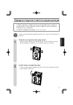
Страница 36: ...passer de plusieurs mm hors du mur afin que vous puissiez suspendre le support à base sur les têtes des vis Suspendez le support à base sur les vis installées assurez vous que le support ne soit pas penché vers la gauche ou vers la droite puis serrez fermement les vis Fixez les vis vendues dans le commerce dans les trous de vis restants 14 à 18 vis Utilisez une vis possédant une hauteur de tête de...

Страница 37: ...t la position du centre de l écran du téléviseur 3 Alignez ce repère sur le centre de l affichage estampé sur le support à base puis montez le support à base sur le mur 4 Après avoir monté l unité de support pour montage mural sur le téléviseur LCD utilisez les repères de dimensions marqués sur le mur 4 coins du téléviseur pour monter le téléviseur sur le support à base 5 Retirez les repères de ru...

Страница 38: ...nd la goupille située tout en haut de l unité de support principal se trouve dans la deuxième rainure à partir du haut du support à base indiquée par un 0 jaune Voir l illustration ci dessous La ligne d alignement qui marque le centre de l écran de télévision sur le support pour montage mural est aussi à la position standard de 0 cm Repères de hauteur marqués sur le côté du support à base Vert Jau...

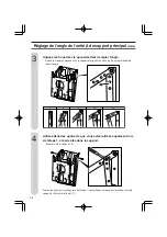
Страница 39: ...our montage mural a été pré assemblée avec le réglage en position verticale 0 dans l emballage il faut donc procéder comme suit pour monter le téléviseur avec un angle voulu 5 angles de montage sont réalisables 0 5 10 15 20 1 Ouvrez l unité A de support principal Orientez le support latéral de réglage du téléviseur LCD dans le sens indiqué par la flèche comme montré sur l illustration 2 Attention ...

Страница 40: ...qui permettent de régler l angle Utilisez deux des quatre vis que vous aviez retirées auparavant lors de l étape 1 et serrez les dans le support Exemple Pour régler à 15 3 4 1 0 5 5 0 5 1 5 0 2 0 0 5 10 15 20 1 0 5 0 1 5 10 20 0 2 0 0 10 10 1 0 10 20 5 0 15 10 20 5 0 15 10 20 5 0 15 15 1 5 10 20 5 0 15 20 5 0 15 20 Toutes les quatre vis retirées lors de l étape 1 sont utilisées uniquement lorsqu o...

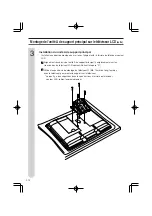
Страница 41: ...au mur sur le téléviseur couleur LCD placez le téléviseur couleur LCD face vers le bas sur un chiffon mou ou sur un coussin Vous pouvez aussi retirer le support du modèle 52 pouces lorsque celui ci est en position debout toutefois l explication est donnée pour la position couchée à laquelle il est plus facile de monter le support pour montage mural Lorsque vous soulevez le téléviseur ne le saisiss...

Страница 42: ...ouleur LCD 1 Alignez les trous de vis de l unité A de support principal 4 emplacements sur les trous du dos du téléviseur LCD couleur Portant le repère A 2 Utilisez les quatre vis de montage du téléviseur B M6 12 mm de long fournies avec le téléviseur pour monter le support sur le téléviseur Lorsqu il y a des capuchons dans les quatre trous à l arrière du téléviseur couleur LCD retirez les préalab...

Страница 43: ...rincipal sur l unité A de support principal Alignez l unité B de support principal sur les trous des vis du support auxiliaire de l unité B de support principal et joignez les à l aide des deux vis fournies A M5 8 mm de long Utilisez les six vis fournies C M4 6 mm de long pour joindre l unité A de support principal et l unité B de support principal 3 2 1 ...

Страница 44: ...place en utilisant les deux vis M4 6 mm de long que vous aviez retirées auparavant lors de l étape 1 5 cm vers le haut 5 cm vers le bas Réglage 0 Repère 5 Vert Repère 5 Bleu Repère 0 Jaune 2 Veillez à effectuer les étapes 1 et 2 ci dessous Si le levier de connexion du support pour montage mural n est pas fixé le téléviseur LCD risquerait de tomber et de blesser quelqu un À l expédition les vis du ...

Страница 45: ...et les leviers de connexion du support pour montage au mur Veillez à le faire absolument 2 Pour modifier l angle à partir de la position d angle réglée actuellement procédez comme expliqué à la page 8 dans la section Réglage de l angle de l unité A de support principal avant d entreprendre les travaux d assemblage Pour effectuer le réglage à la position verticale 0 utilisez toutes les quatre vis r...

Страница 46: ...n des Basishalters an der Wand D 4 Einstellen des Winkels der Haupthaltereinheit A D 7 Befestigen der Haupthaltereinheit A am LCD Fernsehgerät D 9 Befestigen der Haupthaltereinheit B an Haupthaltereinheit A D 11 Einstellen der Wandhalter Verbindungsplatte D 12 Montage des LCD Farbfernsehgerätes an der Wand D 13 ...

Страница 47: ...gewährleisten Eine Missachtung dieser Anzeigen und Aufkleber sowie unsachgemäßer Gebrauch des Produkts können die nachstehend klassifizierten Gefahren mit sich bringen Bitte lesen Sie die folgenden Angaben zu den Warnsymbolen durch bevor Sie den Rest dieses Abschnitts lesen und halten Sie sich unbedingt an alle Anweisungen Bedeutung des Symbols Warnung Eine Missachtung dieser Anweisungen kann Tod ...

Страница 48: ...lche Arbeiten spezialisiert ist Der Kunde sollte von einem Installationsversuch des Fernsehgerätes Abstand nehmen Sharp übernimmt keine Haftung für Unfälle Sachschäden oder Verletzungen die auf unsachgemäße Installation zurückzuführen sind An den Handwerker Um die Sicherheit des Kunden zu gewährleisten muss bei der Installation darauf geachtet werden dass die Wand stabil genug ist um das Gewicht d...

Страница 49: ... Sichtlinie sowie optische und akustische Entfernung in Erwägung gezogen haben Sharp übernimmt keine Haftung für Schäden usw die durch Herunterfallen des LCD Farbfernsehgerätes wegen unzureichender Installationsfestigkeit oder unsachgemäßer Installation verursacht werden Gewichttabelle Einheit kg Installationsort Bitte auch die folgenden Teile verwenden Vorsicht LC 42GX1W LC 42GX2W LC 46GX1W LC 46...

Страница 50: ...ein Die Schraubenköpfe sollten dabei mehrere Millimeter weit von der Wand überstehen so dass der Basishalter an die Schrauben gehängt werden kann Hängen Sie den Basishalter an die installierten Schrauben prüfen Sie dass er gerade hängt und ziehen Sie dann die Schrauben fest an Befestigen Sie den Basishalter mit den im Handel gekauften Schrauben an den restlichen Schraubenlöchern 14 bis 18 Schraube...

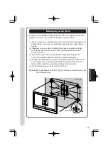
Страница 51: ... Schnittpunkt der Linien markieren Dies ist die Position der Mitte des Fernsehschirms 3 Diese Markierung auf die am Basishalter aufgeprägte Displaymitte ausrichten und dann den Basishalter an der Wand befestigen 4 Nachdem der Wandhalter am LCD Fernsehgerät befestigt worden ist das Fernsehgerät unter Verwendung der Abmessungsmarkierungen an der Wand 4 Ecken des Fernsehgeräts am Basishalter montiere...

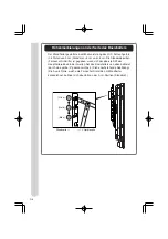
Страница 52: ...enn sich der oberste Stift der Haupthaltereinheit in der zweiten Nut des Basishalters von oben befindet durch eine gelbe 0 gekennzeichnet Siehe nachstehende Abbildung Die Ausrichtlinie welche die Fernsehschirmmitte am Wandhalter kennzeichnet befindet sich ebenfalls an der 0 cm Position Standard Höhenmarkierungen an der Seite des Basishalters Grün Gelb Blau Wandseite TV Geräteseite ...

Страница 53: ...ufbewahren damit sie nicht verloren gehen Die Wandhaltereinheit wurde bei der Verpackung auf die Senkrechtstellung 0 vormontiert Daher muss das folgende Verfahren angewandt werden um das Fernsehgerät zu neigen 5 Winkel sind verfügbar 0 5 10 15 20 1 Haupthaltereinheit A öffnen Den Halter auf der Seite des LCD Fernsehgeräts in Pfeilrichtung ausrichten wie in der Abbildung gezeigt 2 Vorsicht Achten S...

Страница 54: ... der Markierungen am Halter ausrichten 2 der in Schritt 1 entfernten 4 Schrauben in den Halter eindrehen Beispiel Bei Einstellung auf 15 3 4 1 0 5 5 0 5 1 5 0 2 0 0 5 10 15 20 1 0 5 0 1 5 10 20 0 2 0 0 10 10 1 0 10 20 5 0 15 10 20 5 0 15 10 20 5 0 15 15 1 5 10 20 5 0 15 20 5 0 15 20 Alle 4 der in Schritt 1 entfernten Schrauben werden nur dann verwendet wenn der Halter auf die vormontierte Senkrech...

Страница 55: ... Bewahren Sie die entfernten Ständer Befestigungsschrauben 4 Stück auf Verlegen Sie die Kabel Die Anschlussabdeckung entfernen die Kabel anschließen und dann die Abdeckung wieder anbringen 1 2 Wenn Sie den Wandhalter am LCD Farbfernsehgerät montieren legen Sie das LCD Farbfernsehgerät mit der Bildschirmseite nach unten auf ein weiches Tuch oder Kissen Der Ständer kann auch im stehenden Zustand vom...

Страница 56: ...rätes 1 Die Schraubenlöcher der Haupthaltereinheit A 4 Stellen auf die Löcher in der Rückseite des LCD Farbfernsehgeräts ausrichten Prägung A 2 Den Halter mit den 4 im Lieferumfang des Fernsehgeräts enthaltenen TV Installationsschrauben B M6 12 mm Länge am Fernsehgerät befestigen Wenn sich Kappen in den 4 Löchern auf der Rückseite des LCD Farbfernsehgerätes befinden sind diese zuvor zu entfernen 3...

Страница 57: ...ltereinheit B an Haupthaltereinheit A Die Haupthaltereinheit B auf die Schraubenlöcher im Hilfshalter der Haupthaltereinheit B ausrichten und die Teile mit den mitgelieferten 2 Schrauben A M5 8 mm Länge zusammenmontieren Die Haupthaltereinheiten A und B mit den 6 mitgelieferten Schrauben C M4 6 mm Länge zusammenmontieren 3 2 1 ...

Страница 58: ...n Schritt 1 entfernten 2 Schrauben M4 6 mm Länge befestigen 5 cm höher 5 cm tiefer 0 Stellung Markierung 5 Grün Markierung 5 Blau Markierung 0 Gelb 2 Führen Sie die nachstehenden Schritte 1 und 2 aus Falls die Wandhalter Verbindungsplatte nicht befestigt wird kann das LCD Fernsehgerät herunterfallen und jemanden verletzen Die Schrauben der Wandhalter Verbindungsplatte wurden vor dem Versand in die...

Страница 59: ...erbindungsplatten mit den Schrauben befestigen Diesen Schritt unbedingt ausführen 2 Um den Winkel von der gegenwärtig eingestellten Winkelposition zu ändern lesen Sie die Erläuterung auf Seite 8 Einstellen des Winkels der Haupthaltereinheit A durch bevor Sie die Montagearbeit durchführen Um das Fernsehgerät in die Senkrechtstellung 0 zu bringen verwenden Sie alle 4 der gemäß den Anweisungen auf Se...

Страница 60: ...red ES 4 Ajuste del ángulo de la unidad de ménsula principal A ES 7 Monte la unidad de ménsula principal A en el televisor de cristal líquido ES 9 Monte la unidad de ménsula principal B en la unidad de ménsula principal A ES 11 Instale la palanca de conexión de ménsula de montaje en la pared ES 12 Instalación de la pantalla de cristal líquido del TV color en la pared ES 13 ...

Страница 61: ...uetas para garantizar el uso seguro Si no se respetan estas indicaciones y etiquetas y se utiliza incorrectamente el producto puede tener los resultados clasificados a continuación Lea la siguiente información de los símbolos de advertencia antes de leer el resto de esta sección y asegúrese de respetar estrictamente todas las instrucciones Significado del símbolo Advertencia Si no se siguen estas ...

Страница 62: ...hágalo instalar por un técnico cualificado en la instalación El cliente no debe tratar de instalar el TV Sharp no se hace responsable por una mala instalación o accidentes daños o heridas derivadas de una mala instalación Al técnico Para garantizar la seguridad del cliente realice el diseño de tal forma que la fuerza del lugar de instalación sea lo suficientemente fuerte como para soportar el peso...

Страница 63: ...nea de visión y la gama visual y auditiva Sharp no se hace responsable por daños etc provocados porque se caiga la pantalla de cristal líquido del TV color debido a que no se instaló con suficiente fuerza o porque estaba mal instalada Tabla de pesos Unidad kg Lugar de instalación Utilice lo siguiente LC 42GX1W LC 42GX2W LC 46GX1W LC 46GX2W LC 52GX1W LC 52GX2W LC 46XD1E LC 46XD1RU LC 52XD1E LC 52XD...

Страница 64: ...deben sobresalir varios mm encima de la pared para que la ménsula de la base pueda colgar sobre las cabezas de tornillo Cuelgue la ménsula de la base en los tornillos instalados verificando para asegurarse que la ménsula no esté hacia la izquierda o derecha y apriete firmemente los tornillos Utilice tornillos comprados para asegurar los demás orificios de tornillo 14 a 18 tornillos Utilice un dest...

Страница 65: ... marcas de esquina y marque la intersección de las líneas Esta es la posición del centro de la pantalla de TV 3 Alinee esta marca con el centro de la pantalla estampado en la ménsula de base y monte la ménsula de base en la pared 4 Después de montar la unidad de ménsula de montaje en la pared al televisor de cristal líquido utilice las marcas de dimensión en la pared 4 esquinas del TV para instala...

Страница 66: ...pasador superior de la unidad de ménsula principal está en la segunda ranura de la parte superior de la ménsula de base mostrado por un 0 en amarillo Vea la figura de abajo La línea de alineación que marca el centro de la pantalla del televisor en la ménsula de montura está también en la posición de 0 cm normal Marcas de altura en el lado de la ménsula de base Verde Amarillo Azul Lado de pared Lad...

Страница 67: ...de ménsula de montaje en a pared está armado previamente para el ajuste de posición vertical 0 antes de colocarlo en su caja y debe utilizar el siguiente procedimiento para instalar el TV en un ángulo Hay 5 ángulos posibles 0 5 15 20 1 Abra la unidad de ménsula principal A Apunte la ménsula lateral de ajuste del televisor de cristal líquido en el sentido de la flecha tal como aparece en la figura ...

Страница 68: ...illos que fijan el ángulo Utilice 2 de los 4 tornillos que se desmontaron en el paso 4 y apriételos en la ménsula Ejemplo cuando ajusta el ángulo a 15 3 4 1 0 5 5 0 5 1 5 0 2 0 0 5 10 15 20 1 0 5 0 1 5 10 20 0 2 0 0 10 10 1 0 10 20 5 0 15 10 20 5 0 15 10 20 5 0 15 15 1 5 10 20 5 0 15 20 5 0 15 20 Todos los 4 tornillos desmontados en el paso 1 se utiliza sólo cuando vuelva la ménsula al estado orig...

Страница 69: ...ha Guarde los tornillos de fijación 4 tornillos del soporte quitados Haga el trabajo de cableado Abra la cubierta de terminales coloque los cables y vuelva a cerrar la cubierta 1 2 Cuando instale la ménsula de montaje en la pared en la pantalla de cristal líquido del TV color coloque la pantalla de cristal líquido del TV color cara abajo sobre un paño suave o almohadón El soporte también puede des...

Страница 70: ...a pantalla de cristal líquido del TV color 1 Alinee los orificios de tornillo de la unidad de ménsula principal A 4 lugares en los orificios detrás del TV color de cristal líquido estampados A 2 Utilice los 4 tornillos de instalación del TV B M6 longitud de 12 mm que vinieron con el TV para montar la ménsula en el TV Hay tapas en los 4 orificios en el lado trasero del TV color de cristal líquido d...

Страница 71: ... de ménsula principal A Alinee la unidad de ménsula principal B con los orificios de tornillo en la unidad de ménsula auxiliar de la unidad de ménsula principal B y apriételos utilizando los 2 tornillos incluidos A M5 longitud de 8 mm Utilice los 6 tornillos incluidos C M4 longitud de 6 mm para apretar entre sí la unidad de ménsula principal A y la unidad de ménsula principal B 3 2 1 ...

Страница 72: ...s 2 tornillos M4 longitud de 6 mm desmontados en el paso 1 para apretarlos en su lugar Arriba 5 cm Abajo 5 cm Ajuste 0 Marca 5 Verde Marca 5 Azul Marca 0 Amarillo 2 Asegúrese de realizar los pasos 1 y 2 a continuación Si no se fija la palanca de conexión de ménsula de montaje en la pared el televisor de cristal líquido puede caerse y herir a alguien Los tornillos de la palanca de conexión de ménsu...

Страница 73: ...apretar la unida de ménsula principal y las palancas de conexión de ménsula de montaje en la pared Asegúrese de hacer esto 2 Para cambiar el ángulo de la posición de ángulo actual consulte la explicación en la página 8 Ajuste del ángulo de la unidad de ménsula principal A antes de realizar el trabajo de armado Cuando ajuste a la posición vertical 0 utilice todos los 4 tornillos desmontados de acue...

Страница 74: ......

Страница 75: ...CH 1 ...

Страница 76: ...CH 2 ...

Страница 77: ...CH 3 ...

Страница 78: ...CH 4 ...

Страница 79: ...CH 5 ...

Страница 80: ...CH 6 ...

Страница 81: ...CH 7 ...

Страница 82: ...CH 8 ...

Страница 83: ...CH 9 ...

Страница 84: ...CH 10 ...

Страница 85: ...CH 11 ...

Страница 86: ...CH 12 ...

Страница 87: ...CH 13 ...

Страница 88: ...leitung ist aus Recyclingpapier hergestellt Este manual de manejo se imprimió en papel reciclado この印刷物は環境に配慮した植物性大豆油イ ンキを使用しています フリーダイヤルがご利用いただけない場合は 東日本相談室 西日本相談室 0120 078 178 TEL 043 351 1821 FAX 043 299 8280 TEL 06 6792 1582 FAX 06 6792 5993 261 8520 千葉県千葉市美浜区中瀬1 9 2 581 8585 大阪府八尾市北亀井町3 1 72 お 客 様 相 談 セ ン タ ー 修理のご相談は 16ページ記載の お客様ご相談窓口のご案内 をご参照ください http www sharp co jp シャープホームページ 545 8522 329 2...

Отзывы: