


Ref. No.
Part No.
Description
Code
Ref. No.
Part No.
Description
Code
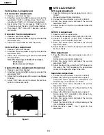
24
26MR70
TRANSFORMERS
T601
RTRNZ0057PEZZ
R Transformer
AK
or
RTRNZ0731CEZZ
T602
RTRNF0049MEZZ X H-Volt Transformer
AY
T702
RTRNW0001GJZZ X Transformer
AN
CONTROLS
R738
RVR-M4 X 22k (B) 130V Adj.
AE
or
RVR-M4628GEZZ
or
RVR-M4336CEZZ
CAPACITORS
[EL. ··· Electrolytic, M-Poly.··· Metalized Polypro Film]
C51
VCEA0A1AW108M J 1000 10V
EL.
AC
C53
VCEA0A1HW105M J 1.0
50V
EL.
AB
C54
VCEA0A1HW475M J 4.7
50V
EL.
AB
C101
VCEA0A1CW476M J 47
16V
EL.
AB
C201
VCKYCY1HF103Z
J 0.01
50V
Ceramic
AA
C202
VCKYCY1HF103Z
J 0.01
50V
Ceramic
AA
C203
VCKYCY1HF103Z
J 0.01
50V
Ceramic
AA
C204
VCQYTA1HM223K J 0.022 50V
Mylar
AB
C205
VCKYCY1HB103K J 0.01
50V
Ceramic
AA
C206
VCKYCY1HB102K J 1000p 50V
Ceramic
AA
C207
VCEA0A1CW476M J 47
16V
EL.
AB
C208
VCKYCY1HF103Z
J 0.01
50V
Ceramic
AA
C209
VCEA0A1HW105M J 1.0
50V
EL.
AB
C210
VCEA0A1HW474M J 0.47
50V
EL.
AB
C212
VCEA0A1HW474M J 0.47
50V
EL.
AB
C220
VCKYCY1EF104Z
J 0.1
25V
Ceramic
AA
C301
VCCCCY1HH220J J 22p
50V
Ceramic
AA
C302
VCKYCY1HB102K J 1000p 50V
Ceramic
AA
C303
VCCCCY1HH331J J 330p 50V
Ceramic
AA
C304
VCCCCY1HH220J J 22p
50V
Ceramic
AA
C305
VCKYCY1HB103K J 0.01
50V
Ceramic
AA
C356
VCKYCY1HB332K J 3300p 50V
Ceramic
AA
C357
VCEA0A1HW106M J 10
50V
EL.
AB
C358
VCEA0A1HW106M J 10
50V
EL.
AB
C361
VCEA0A1CW227M J 220
16V
EL.
AC
C411
VCEA0A1AW108M J 1000 10V
EL.
AC
C412
VCKYCY1HF103Z
J 0.01
50V
Ceramic
AA
C414
VCEA0A1HW225M J 2.2
50V
EL.
AB
C416
VCEA0A1HW105M J 1.0
50V
EL.
AB
C451
VCQYTA1HM104K J 0.1
50V
Mylar
AC
C454
VCEA0A1HW475M J 4.7
50V
EL.
AB
C456
VCEA0A1HW106M J 10
50V
EL.
AB
C491
VCEA0A1CW107M J 100
16V
EL.
AC
C492
VCKYCY1HF103Z
J 0.01
50V
Ceramic
AA
C510
VCEA0A1VW477M J 470
35V
EL.
AB
C511
VCCSPA2HL180K
J 18p
500V Ceramic
AA
C512
VCFYSA X 0.22
63V
Mylar
AF
C513
VCFYSA1JB473J
J 0.047 63V
Mylar
AC
C514
VCEA0A1VW477M J 470
35V
EL.
AB
C515
VCEA0A1HW475M J 4.7
50V
EL.
AB
C516
VCKYCY1HB222K J 2200p 50V
Ceramic
AA
C517
VCEA0A1CW226M J 22
16V
EL.
AB
C520
VCEA0A1HW107M J 100
50V
EL.
AB
C530
VCFYFA1HA334J
J 0.33
50V
Mylar
AB
C531
VCFYFA1HA564J
J 0.56
50V
Mylar
AB
C606
VCKYPA2HB561K
J 560p 500V Ceramic
AA
C607
VCKYPA1HB472K
J 4700p 50V
Ceramic
AA
C610
RC-FZ1018CEZZ
X 12600p 1.8kV Plastic
AG
C612
VCFPVC2DB514J
X 0.51
200V M-Poly.
AF
C632
VCKYCY1EB153K J 0.015 25V
Ceramic
AA
C633
VCEA0AX 330
10V
EL.
AE
C634
VCKYCY1HF103Z
J 0.01
50V
Ceramic
AA
C635
VCEA0A1HW105M J 1.0
50V
EL.
AB
C637
VCEA0A1CW476M J 47
16V
EL.
AB
C652
VCEA0A1HW475M J 4.7
50V
EL.
AB
C653
VCEA0A1HW105M J 1.0
50V
EL.
AB
C654
VCFYSA1HB184J
J 0.18
50V
Mylar
AB
C662
VCEA0A1CW477M J 470
16V
EL.
AC
C701
RC-FZ037SCEZZ
J 0.22
AC250V Plastic
AD
or
RC-FZ012SGEZZ
or
RC-FZ017SGEZZ
or
RC-FZ029SGEZZ
C702
RC-KZ0029CEZZ
J 0.01
AC250V Ceramic
AC
or
RC-KZ0016CEZZ
C703
RC-KZ0029CEZZ
J 0.01
AC250V Ceramic
AC
or
RC-KZ0016CEZZ
C705
RC-EZ1336CEZZ
J 560
200V EL.
AQ
or
RC-EZ0800CEZZ
C706
RC-KZ0092GEZZ
J 0.0033 AC250V Ceramic
AC
or
RC-KZ021SCEZZ
or
RC-KZ009SCEZZ
or
RC-KZ0106GEZZ
C710
VCKYPH3DB561K J 560p 2kV
Ceramic
AC
or
RC-KZ0338CEZZ
C717
VCKYPA2HB472K
J 4700p 500V Ceramic
AB
C723
RC-EZ0724CEZZ
J 100
160V EL.
AG
C725
RC-EZ0809CEZZ
J 220
160V EL.
AL
C726
VCKYPH3DB561K J 560p 2kV
Ceramic
AC
or
RC-KZ0338CEZZ
C727
VCKYPA2HB472K
J 4700p 500V Ceramic
AB
C730
VCEA0A1CW108M J 1000 16V
EL.
AD
C731
VCEA0A1EW337M J 330
25V
EL.
AC
C732
VCKYCY1HF103Z
J 0.01
50V
Ceramic
AA
C736
VCKYCY1HF103Z
J 0.01
50V
Ceramic
AA
C737
VCEA0A1EW226M J 22
25V
EL.
AB
C738
RC-KZ0040CEZZ
J 820p 2kV
Ceramic
AD
or
RC-KZ0340CEZZ
C739
VCEA0A1HW104M J 0.1
50V
EL.
AB
C740
VCEA0A1EW476M J 47
25V
EL.
AB
C742
VCKYPA2HB102K
J 1000p 500V Ceramic
AA
C743
VCKYPH3DB561K J 560p 2kV
Ceramic
AC
or
RC-KZ0338CEZZ
C750
VCKYCY1HF103Z
J 0.01
50V
Ceramic
AA
C753
VCKYPH3DB561K J 560p 2kV
Ceramic
AC
or
RC-KZ0338CEZZ
C754
VCEA0A1CW476M J 47
16V
EL.
AB
C758
VCEA0A2EW106M J 10
250V EL.
AD
C760
VCEA0A1CW108M J 1000 16V
EL.
AD
C771
VCEA0A1CW476M J 47
16V
EL.
AB
C772
VCEA0A1CW476M J 47
16V
EL.
AB
C783
VCQYTA1HM103K J 0.01
50V
Mylar
AB
C784
VCKYCY1HF103Z
J 0.01
50V
Ceramic
AA
C801
VCCCCY1HH180J J 18p
50V
Ceramic
AA
C807
VCKYCY1EF104Z
J 0.1
25V
Ceramic
AA
C808
VCEA0A1HW106M J 10
50V
EL.
AB
C809
VCEA0A1HW105M J 1.0
50V
EL.
AB
C811
VCKYCY1CB473K J 0.047 16V
Ceramic
AA
C812
VCEA0A1HW474M J 0.47
50V
EL.
AB
C901
VCEA0A1HW105M J 1.0
50V
EL.
AB
C925
VCEA0A1HW106M J 10
50V
EL.
AB
C1401 VCKYCY1EF104Z
J 0.1
25V
Ceramic
AA
C1402 VCKYCY1EF104Z
J 0.1
25V
Ceramic
AA
C1403 VCEA0A1CW476M J 47
16V
EL.
AB
C1405 VCEA0A1HW106M J 10
50V
EL.
AB
C1406 VCEA0A1HW106M J 10
50V
EL.
AB
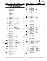
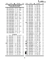
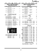
PWB-A: DUNTKA462WEV6
MAIN UNIT (Continued)
!
!
!
!
!
!
!
!
!
!
!
Содержание 26MR70
Страница 11: ...11 6 5 4 3 2 1 A B C D E F G H 26MR70 CHASSIS LAYOUT PWB A PWB B ...
Страница 12: ...12 6 5 4 3 2 1 A B C D E F G H 26MR70 BLOCK DIAGRAM ...
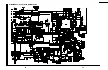
Страница 14: ...15 26MR70 14 12 11 10 9 8 7 6 5 4 3 2 1 A B C D E F G H SCHEMATIC DIAGRAM MAIN 1 Unit ...
Страница 15: ...17 26MR70 16 12 11 10 9 8 7 6 5 4 3 2 1 A B C D E F G H SCHEMATIC DIAGRAM MAIN 2 Unit ...
Страница 16: ...18 6 5 4 3 2 1 A B C D E F G H 26MR70 SCHEMATIC DIAGRAM CRT Unit ...
Страница 17: ...19 6 5 4 3 2 1 A B C D E F G H 26MR70 PRINTED WIRING BOARD ASSEMBLIES PWB B CRT Unit Wiring Side ...
Страница 18: ...20 6 5 4 3 2 1 A B C D E F G H 26MR70 PWB A MAIN Unit Wiring Side ...
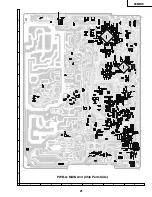
Страница 19: ...21 6 5 4 3 2 1 A B C D E F G H 26MR70 PWB A MAIN Unit Chip Parts Side ...


